INTRODUCTION
The emotional and functional challenges of maxillary removable complete dentures are culturally well-documented. More patients with remaining periodontally healthy mandibular teeth and fully edentulous patients, in all age groups, are seeking fixed alternatives. However, current protocols for conversion of a maxillary denture to an implant-supported prosthesis are often time-consuming, imprecise, and fraught with pitfalls relating to cantilever engineering, implant angulation, acrylic fracture, and abutment-retention methods.
The “All-on-4” approach for restoring a completely edentulous arch is well-validated in the literature, in the context of overcoming anatomic limitations to provide tooth- and tissue-borne restorative solutions for fully edentulous patients. The efficacy of All-on-4 (Nobel Biocare) prosthetics in maximizing anterior-posterior (A-P) spread, optimizing load distribution,1 and the maxillary All-on-4 shelf2 (similar to the current case), are well-documented.
Bambara3 provided an early overview of hybrid implant-retained prosthetic treatment planning, presenting a maxillary All-on-4 case example. Phillips4 provided foundational insights via an immediate conversion case, featuring adaptation of a mandibular denture over 5 temporary anterior abutments, during staged implant healing.
Tischler et al5 reviewed available options and challenges that accompany implant-supported and -retained prostheses, correctly citing issues with hybrids (acrylic fracture, show-through of any metal substructure) and recommending the monolithic zirconia bridge as an ideal definitive implant-supported full-arch solution.
Providing both surgical and prosthetic phases for fabrication of high-quality interim fixed hybrid conversion prosthetics—in a single appointment—is an attractive option for the general restorative dentist and surgical specialist alike and is well suited to the interdisciplinary dentofacial team environment. The case presented here illustrates key streamlining features that combine cone beam computed tomography (CBCT), implant-planning software, 3-D-printed multifunctional surgical stents, and a novel swivel-abutment attachment that expands flexibility of use with convergent or divergent implant placement.
CASE REPORT
Diagnosis and Treatment Planning
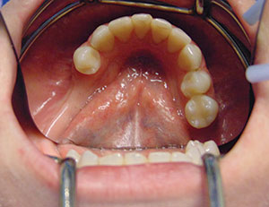
A healthy 29-year-old female (a patient-service staff member in the author’s practice) had lost all of her maxillary teeth approximately one year previously due to poor oral hygiene habits. She presented with a maxillary complete denture and a lower partial denture. She was extremely unhappy wearing removable prosthetics and wished to explore fixed options. Her oral hygiene had improved dramatically during her tenure in this position, and her lower teeth remained periodontally stable as of her last recare visit (Figures 1 and 2). She was a nonsmoker in good overall health with no prescribed medications.
 |
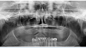 |
| Figure 1. The remaining periodontally healthy mandibular dentition. | Figure 2. Preoperative panoramic radiograph. |
A comprehensive evaluation included a radiographic work-up, diagnostic casts, and intra- and extraoral examinations (including a screening for oral cancer and other abnormalities). No temporomandibular dysfunction (TMD) issues were noted. CBCT scans of (1) the patient wearing a diagnostic wax try-in that included radiographic markers (made using her existing denture) and (2) the wax try-in alone were performed. The scan data were uploaded into a commercial implant-planning software application (360dps [360 Imaging]) and evaluated. The subsequent computer-facilitated treatment plan was reviewed with the 360 Imaging team and a consulting oral-maxillofacial radiologist. Overdenture options; the advantages and disadvantages of hybrids; and options involving bone grafting with sinus augmentation, or zygomatic implants, were discussed.
The patient gave written informed consent for the procedure described here in full compliance with the Health Insurance Portability and Accountability Act of 1996 (HIPAA).
In this practice, numerous core variables are routinely assessed when planning a fixed denture-conversion case, including:
- Bone availability;
- Proper implant placement within the implant-planning software;
- The amount of vertical dimension of occlusion (VDO) needed for prosthesis strength;
- The appropriate planning of the cosmetic aspects inherent in the transition between the acrylic prosthesis base and alveolar mucosa;
- Papilla-meter measurements;
- Radiographic overlay of the wax try-in for implant position;
- Multiple positioned pictures and patient expectations;
- How many implants are clinically possible and feasible;
- A review of the options for one or 2 additional implants, including the required angulation to accommodate A-P spread;
- The patient’s history of bruxism, including wear on the opposing dentition; and
- The patient’s overall health, facial muscle architecture, gender, and stature.
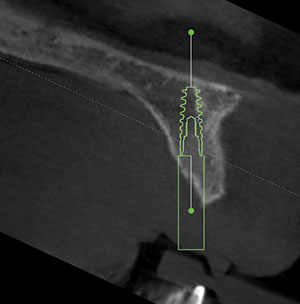
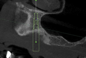
After a collaborative discussion with the patient, the decision was made to place 4 implants, with the posterior fixtures approximating a 30º angle that mirrored the anterior wall of her maxillary sinus to support an interim hybrid prosthesis, produced using a same-day denture conversion. In conjunction with position Nos. 8 and 9, the distalmost implants that required a 30º angulation were planned for the approximate positions of the first premolars (Figures 3 to 5). The associated A-P spread (10.0 mm) was compatible with a one-tooth cantilever modulus and the patient’s limited remaining mandibular dentition. This design provided cantilever length (CL)/A-P spread ratios of 1.4 (left) and 1.5 (right), which is consistent with the value of 15.0 mm proposed by Ratcliff6 as being the maximum CL for a hybrid prosthesis that is supported by implants and has an A-P spread of 10.0 mm (as in the current case). CL/A-Pratios of 0.5 to 0.6 were reported for full-arch acrylic interim prostheses in a 2-year retrospective analysis by Drago7 to predict consistent, successful function during that period. While these ratios are considerably lower than those of the current case, these prostheses followed a typical All-on-4 protocol and were all screw-retained, unlike the flexible swivel attachments used here.
 |
 |
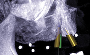
| Figure 3. CBCT image showing guided placement of the implant in position No. 9. |
Figure 4. CBCT image showing guided placement of the implant in position No. 12. |
 |
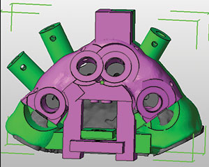 |
| Figure 5. CBCT image showing prospective implant positions relative to available maxillary bone volume. | Figure 6. 3-D software graphic showing the bone-reduction guide and retention pin positions (green) and the implant-placement surgical guide with stabilizing vertical mount (purple). |
The final prosthesis planned for the patient will be a monolithic zirconia implant-retained fixed All-on-4 hybrid. The design of this prosthesis will consider the results of the 4-year retrospective study by Drago8, which showed a near-100% survival rate for maxillary All-on-4 cantilevered hybrids that had an average maxillary A-P spread of 18.4 mm, CL/A-P spread ratios of 0.85 (right) and 0.84 (left), and posterior implant angulations similar to those in the current case. Again, these prostheses were all screw-retained, unlike the current case, which uses spherically geometric attachments capable of omnidirectional rotation and stress distribution.
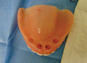
With mindfulness of these variables, a denture was fabricated for conversion, with one premolar and one molar on each quadrant. The resulting aesthetics were tested in a functional wax try-in, which provided an acceptable fill of the buccal corridor. Dual stents (Bone Reduction Guide [360 Imaging]) were 3-D- fabricated to facilitate both guided alveoloplasty and fully guided implant placement (Figure 6). These stents corresponded with the NobelActive Guided Surgery Kits. Using these measurements, 6.0 mm of vertical height was removed from the diagnostic cast and the denture for conversion was fabricated.
Based upon the data generated by the software and obtained via clinical jaw-relation and laboratory diagnostic records, removal of 6.0 mm of maxillary bone height was confirmed to be appropriate to provide 16.0 mm of interocclusal vertical space for optimal prosthetic strength, cosmetic blending of the aesthetically critical mucosa-prosthesis transition line, and appropriate structural and anatomic placement of the implants into the existing bony architecture.
Measurements of the approximate biotype thickness in the proposed sites were made using a periodontal probe and an endodontic stopper. These were used for proactive ordering of the abutment cuff height (LOCATOR F-Tx [Zest Dental Solutions]).
 |
 |
| Figure 7. Midcrestal incision and palatal mucoperiosteal flap reflection prior to guided alveoloplasty. | Figure 8. The surgical guide and retention pins in place over vertical mount, post-alveoloplasty. |
 |
 |
| Figure 9. The reduction guide and retention pins in place, post-alveoloplasty. | Figure 10. Drilling of a pilot hole for anterior osteotomy, while showing a 2.0-mm key. |
Surgical Protocol
A surgery pack and sterile drape kit (Salvin Dental; Misch Implant Institute), were used for infection control in the room and to prepare the patient.
A Doctors for Oral Conscious Sedation protocol (docseducation.com) was used for anxiolysis. The patient took 10.0 mg of diazepam the night before the procedure, and 0.5 mg of triazolam was administered sublingually 30 minutes prior to the start of the procedure. Her oxygen saturation was monitored throughout the procedure. Flumazenil and an airway kit were ready, if needed.
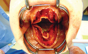
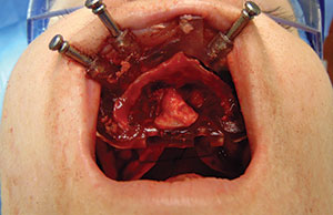
After obtaining profound local anesthesia throughout the maxillary arch using lidocaine (2% with 1:100,000 epinephrine), a full-arch midcrestal incision was made using a No. 15 blade. The palatal mucoperiosteal flap was released, and a crossed suture was placed over the palate to keep the palatal flap margins out of the operative field (Figure 7). A midline buccal vertical release was incised, and the buccal flap was released.
The bone-borne stent comprises 3 separate pieces: (1) a vertical mount that provides an anterior stop prior to pin stabilization, (2) a reduction guide (base) stabilized by the pins, and (3) a surgical guide that locks into the base after alveoloplasty is completed and fully guides osteotomy preparation and implant placement (Figure 8).
The vertical mount and reduction guide are initially seated together; the mount provides a vertical stop for the reduction guide until stabilization pins are placed. The vertical mount was removed and the guided alveoloplasty was completed (Figure 9) with a block contouring kit (Pikos [Salvin Dental])—specifically, using the large round bur to optimize speed while applying copious and continuous irrigation with sterile saline solution (type-1 bone throughout).
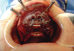
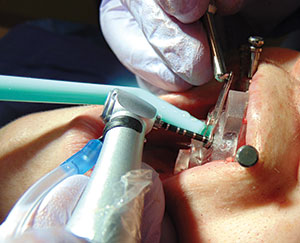
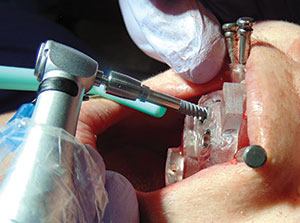
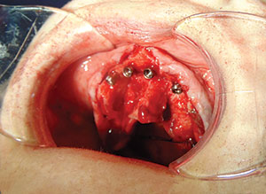
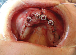
After completion of the alveoloplasty, the surgical guide was locked into place with 3 retention pins (Figure 8). Next, a standard soft-bone drilling protocol (NobelActive [Nobel Biocare] was used to prepare the osteotomies through the guide (Figure 10). Then four 3.5- × 11.5-mm implants (NobelActive) were placed (Figures 11 and 12) at an insertion torque of > 35 Ncm at final placement of each implant. Next, 4 abutments were placed (LOCATOR F-Tx) (Figure 13), and healing caps were secured. Tensionless primary closure of the flap was achieved using 3-0 polytetrafluoroethylene interrupted sutures (Maxima [Henry Schein]).
Prosthetic Phase
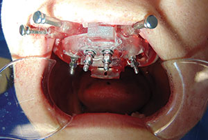
After flap closure, the healing caps were removed, block-out material and spacers (LOCATOR F-Tx) were placed around each abutment, and the denture attachment housings were placed (Figure 14). The LOCATOR F-Tx abutment system used in this case features a retenti
on ball that possesses a unique, spherical coronal geometry (polyetheretherketone, also known as PEEK) that allows omnidirectional rotation of the denture attachment housing; enables correction of up to 40º of convergence or divergence between any 2 implants; and allows the clinician to align the housings as parallel as possible, effectively eliminating the need for angled abutments. An interim processing-ball (black) facilitates insertion and removal during fabrication. Bite registration material (Blu-Bite [Henry Schein]) was placed inside the immediate denture to indicate where the tissue side required relief. A chairside recess bur (Zest Anchors Chairside Overdenture Prep and Polish Kit, Kit item No. 09582. Recess bur No. 09576) and vent burs (Kit item No. 09582. Vent Bur No. 09578) were used to relieve the acrylic in each abutment location on the intaglio of the denture (Figure 15).
 |
 |
| Figure 11. Placement of one of the four 3.5- × 11.5-mm implants (NobelActive [Nobel Biocare]). | Figure 12. Completed placement of all 4 implant fixtures. |
 |
 |
| Figure 13. Completed placement of 4 LOCATOR F-Tx [Zest Dental Solutions] abutments. | Figure 14. Block-out material and spacers (LOCATOR F-Tx) placed around each abutment and denture attachment housings placed. |
 |
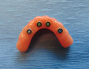 |
| Figure 15. Relief of intaglio acrylic in each abutment location on tissue side of relined denture. | Figure 16. Intaglio view of attachment housings after hard reline and pick-up from abutments. (LOCATOR F-Tx high-retention [green, posterior] and low-retention [blue, anterior] balls.) |
 |
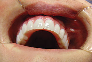 |
| Figure 17. Anterior view of the finished interim prosthesis with attachment housings. | Figure 18. Prosthesis locked into place, showing the level of the mucosa-prosthesis transition line. |
 |
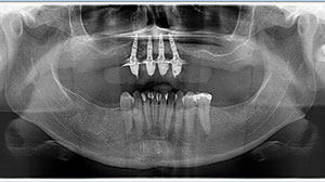 |
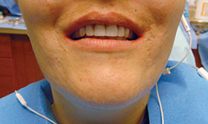
| Figure 19. Postoperative photo of patient with the interim prosthesis in place. | Figure 20. Post-op panoramic radiograph with the interim prosthesis in place. |
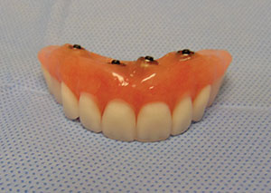
Light-body vinyl polysiloxane material (VP Mix HP Fast Set [Henry Schein]) was used in conjunction with a presurgery bite registration to check and recheck to ensure that the denture was fully seated with no interference. A chair-side hard-attachment material (Zest Dental Solutions) was used to both reline the denture and pick up the attachment housings from the abutments (Figure 16). After completion of pick-up, a prep and polish kit (Chairside Denture Prep and Polish Kit [Zest Dental Solutions]) was used to convert the immediate denture into an acrylic hybrid (Figure 17).
Unlike the final retention balls, the black processing balls (not shown) allow the prosthesis to snap on and off in a manner similar to a Zest LOCATOR overdenture, facilitating the steps of checking and refining the occlusion with the lower dentition, speech, form, and function. All were approved by the clinician and the patient.
Finally, the black processing balls were exchanged for 2 green (high-retention) and 2 blue (low-retention) retention balls (Figure 16), and the prosthesis was locked into place for immediate loading (Figure 18). This system allows for 2 removal methods: (1) hydraulic displacement disengagement and (2) a removal bar-and-loop procedure. In the author’s experience, the removal bar is extremely easy to use and much faster than removing composite and screws (as in a traditional multi-unit abutment prosthesis).
Postoperative evaluations were performed at 24 hours and again at one week, along with monthly hygiene recare visits until the completion of healing. The patient tolerated the procedure well and was very pleased with the result (Figure 19; postoperative panoramic view in Figure 20). A final zirconia hybrid prosthesis (Prettau Zirconia Implant Bridge [Tischler Dental Laboratory]) will eventually be fabricated and delivered to replace the interim conversion denture. Then, after completion of the computer-planned final maxillary zirconia hybrid prosthesis, horizontal ridge augmentation will be envisioned for the lower arch, followed by implant placement to restore the lower posterior dentition.
DISCUSSION
The combination of imaging and computer-facilitated surgical-guidance modalities served to optimize both speed of treatment and patient satisfaction in providing a high-quality interim prosthesis. The entire procedure (including clinical photographs) required approximately 4 hours.
Three factors significantly simplified and expedited this procedure for the clinician, compared with traditional denture conversion protocols:
1. Collaborative 3-D implant treatment-planning software support (360 Imaging) during the pre-surgical planning phase. Data from the CBCT computer-guided implant placement plan enabled accuracy of tissue-supported masticatory load distribution across the distal portions of the prosthesis, in the presence of moderately long cantilever spans (14.0 mm and 15.0 mm, right and left, respectively, measured on the master cast). In turn, this enabled the compatibility of CLs and the appropriate angulation of the 4 implants to produce a functionally balanced hybrid prosthesis.
2.
A 2-stage bone-borne stent (Bone Reduction Guide), comprising both a bone-reduction guide and an implant surgical guide. Reliable pre-treatment CBCT imaging and proper soft-tissue reflection and management are 2 key prerequisites for successful outcome accuracy.
3. The novel LOCATOR F-Tx abutment system used in this case greatly facilitated and simplified the denture-conversion process, compared with the time-consuming and technique-sensitive process of retrofitting an immediate denture onto multi-unit abutments, and then luting the denture onto temporary copings. This system eliminates the need for angled abutments and saves considerable time. Moreover, the temporary prosthesis is not severely weakened by having to drill holes through it, decreasing the chance of acrylic fracture during the healing process. Used in conjunction with validated CBCT-based software-facilitated treatment planning, this attachment flexibility affords effective hybrid design that will accommodate CL of up to 15.0 mm, which is within the guidelines proposed by Ratcliff6 specifically in connection with an A-P spread of 10.0 mm, as was observed here.
CLOSING COMMENTS
This is the first case report of clinical use of the LOCATOR F-Tx attachment in an All-on-4 hybrid application. Obviously, more clinical data from larger studies are needed to assess any influence of such an attachment on stress distribution relative to any combination of CL, A-P spread, and clinical success.
If the clinician is experienced and comfortable with both the surgical and prosthetic aspects of treating a LOCATOR pick-up case, this procedure can be done using the materials and system described in this case. This level of increased simplification potentially enables more restorative dentists to offer their patients this option, thereby working collaboratively with their surgical teams in an interdisciplinary manner.
Acknowledgements
Dr. Dixon wishes to thank his patient for allowing her case to be reported and published; Scott A. Saunders, DDS, ELS, at Dental and Medical Writing and Editing, LLC, (Lancaster, Pa), for professional dental and medical writing and editing services in preparation of the article manuscript; and Dr. Armen Grigoryan, DDS, managing clinical director and partner of Aspen Dental (Venice, Fla), for his assistance with this case.
References
- Chan MH, Holmes C. Contemporary “All-on-4” concept. Dent Clin North Am. 2015;59:421-470.
- Jensen OT, Adams MW, Cottam JR, et al. The All-on-4 shelf: maxilla. J Oral Maxillofac Surg. 2010;68:2520-2527.
- Bambara GE. Treatment planning attachments and implants. Dent Today. 2007;26:56-59.
- Phillips B. The immediate provisional hybrid. Dent Today. 2010;29:122-123.
- Tischler M, Ganz SD, Patch C. An ideal full-arch tooth replacement option: CAD/CAM zirconia screw-retained implant bridge. Dent Today. 2013;32:98-102.
- Ratcliff S. Implants, overdentures and hybrids: rapidly expanding options for the edentulous patient! January, 27, 2017. speareducation.com/spear-review/2015/07/implants-overdentures-and-hybrids-rapidly-expanding-options-for-the-edentulous-patient. Accessed July 17, 2017.
- Drago C. Cantilever lengths and anterior-posterior spreads of interim, acrylic resin, full-arch screw-retained prostheses and their relationship to prosthetic complications. J Prosthodont. 2016 Feb 5. [Epub ahead of print]
- Drago C. Ratios of cantilever lengths and anterior-posterior spreads of definitive hybrid full-arch, screw-retained prostheses: results of a clinical study. J Prosthodont. 2016 Jul 14. [Epub ahead of print]
Dr. Dixon is a graduate of the University of Louisville School of Dentistry in Louisville, Ky, and the Implant Educators Comprehensive Interdisciplinary Implant Continuum (University of Florida College of Dentistry Office of Continuing Education at the Seminole AEGD Clinic). He is majority owner and managing partner of R. Dustin Dixon DMD Holdings, PLLC, operating 12 brand-name Aspen Dental locations throughout southwest Florida. He can be reached at (941) 518-8947 or by email at [email protected].
Disclosure: Dr. Dixon reports no disclosures.
Related Articles
A Mini Dental Implant Alternative to All-on-Four
Attachment System Doesn’t Require Screws or Cement
FDA Approves Material for 3-D Printed Dentures