


INTRODUCTION
Patients with partial or fully edentulous clinical presentations for dental implant reconstruction offer unique challenges for both the implant surgeon and restorative practitioner. The task of restoring any edentate area requires a complete understanding of each patient’s individual anatomy to identify vital structures and volume of bone, avoid complications, and maximize success. There are many choices for the surgeon, restorative clinician, patient, and dental laboratory team to review and accept prior to the scalpel being used. These choices should, therefore, be based on the desired prosthetic outcome in order to achieve true restoratively driven implant reconstruction. Perhaps the most important treatment planning concept involves the ultimate design of the final implant-supported prosthesis, as it will dictate the required number of implants to achieve the desired occlusion, proper implant positioning, cost to the clinician and patient, and prosthetic longevity.
Recent advances in dental materials, innovative CAD/CAM technology, and 3-dimensional (3-D) imaging coupled with interactive treatment planning concepts have provided clinicians with new, predictable alternatives for their patients. This article will highlight the CAD/CAM zirconia screw-retained implant bridge, a prosthetic choice that the authors feel offers many advantages over conventional hybrid-type implant supported restorations (Figure 1). Treatment planning protocols, and surgical, prosthetic, and laboratory steps required to fabricate a CAD/CAM zirconia screw-retained implant bridge will be illustrated.
In this article, the zirconia screw-retained option will be compared to the other implant supported options available, and the background of zirconia as a material will be discussed.
Treatment Planning Considerations: CAD/CAM Full-Arch Screw-Retained Implant Prosthetics
Each case presentation requires a standard diagnostic protocol to ensure a proper understanding of the patient’s existing anatomy, occlusal requirements, interarch space, available bone, phonetics, and functional and aesthetic needs. Initial periapical or panoramic radiographs, intraoral impressions, articulated casts, and preoperative photographs should be an essential part of data collection. A major component of presurgical treatment planning is utilization of cone beam computed tomography (CBCT). Ideally, a diagnostic wax-up or a duplicate of the patient’s denture can be utilized during the scan acquisition to determine the tooth position versus the underlying bone (Figure 2). Additionally, the CBCT scan can offer essential information with regards to the amount of alveoloplasty, need for grafting, position and angulation of implants, and implant length and width, bone density, and much more (Figure 3). A CBCT scan can also be utilized to create a surgical guide or bone reduction guide.1 Even if a guide is not utilized, a CBCT scan can be a major advantage in achieving surgical success.1-4
 |
 |
| Figure 1. The Prettau Zirconia screw-retained CAD/CAM Implant Bridge (Zirconzahn USA). | Figure 2. A diagnostic wax-up of a patient’s denture can show the prosthetic space on a cone beam computed tomography (CBCT) scan. |
When treatment planning an implant supported tooth replacement for a dental arch, the clinician must initially determine how far distally the prosthetic teeth will be positioned.5,6 This is a starting point of both treatment planning and the informed consent process, and a detailed discussion with the patient with respect to aesthetics, chewing ability, and comfort is required. Oftentimes sinus grafting, ridge augmentation, nerve repositioning, or an increased number of implants are needed to gain first or second molar occlusion on the maxillary or mandibular arch.7 Many patients can live comfortably with first molar occlusion or even second premolar occlusion. The shortened dental arch concept is supported in the dental literature as a viable treatment option.8 It is the authors’ experience that once a patient is offered the option of a shortened dental arch versus the additional surgical procedures and expense to gain additional teeth, the shortened dental arch is often chosen. The concept of placing implants between the maxillary sinuses or interforaminally with bilateral distal cantilevers is well established in the literature.9 The number of implants that can be treatment planned varies based upon clinical limitations and whether implants will be placed in a conventional parallel relationship, or tilted in an off-angled position (Figure 4).10 The distal most implants in both arches can be tilted distally to increase the anterior posterior spread.11 Consideration of the amount of angulation of the distal most implants must be had with respect to shear forces on the implants. The amount of prosthetic cantilever that is clinically acceptable is dependent on the anterior/posterior spread and arch form. The patient’s interarch space must be sufficient enough to allow for adequate prosthetic space and material thickness.12
Misch13 classifies a fixed-type restoration designed with increased prosthetic space as an “FP3” prosthesis. In order to increase interarch space and create adequate width for implant placement, it may be necessary to remove vertical bone height. A patient who has lost bone or has had bone surgically reduced through alveoloplasty will present with an increased interarch space. Additionally, an FP3 prosthesis often requires prosthetic replacement of the gingival tissue (Figure 5). Once gingival tissue replacement is a planned option, the clinician must be cognitive of the lip position in relation to the smile-line. Ideally, the junction between the prosthetic flange and natural gingival area should be covered by the patient’s lip when smiling. This requires adequate presurgical prosthetic based planning and coordination.14
 |
 |
| Figure 3. A CBCT scan can offer much valuable information for surgical and prosthetic planning. | Figure 4. Panoramic radiograph showing implants placed between the maxillary sinuses and mental foramens. |
 |
 |
| Figure 5. A CAD/CAM zirconia screw-retained bridge example of an FP3 prosthesis, replacing a patient’s gingival and tooth areas. | Figure 6. A fractured hybrid bridge, showing the susceptibility of acrylic to a patient’s normal chewing habits. |
 |
 |
| Figure 7. A CAD/CAM Prettau Zirconia screw-retained bridge. | Figure 8. Prettau Zirconia CAD/CAM bridge, showing screw holes that are impervious to chipping because of zirconia’s physical properties. |
Prosthetic Options For Implant-Supported Full-Arch Tooth Replacement
There are 5 full-arch implant-supported prosthetic options to replace patients’ teeth: an implant overdenture, a cement retained bridge, an acrylic-fused-to-metal hybrid screw-retained bridge, a PFM hybrid screw-retained bridge, and a zirconia screw-retained bridge.15
Implant Overdentures—An implant-supported overdenture has the advantage of replacing a patient’s teeth with more lenient implant placement positions compared to the other alternative prosthetic choices. The implant denture often allows for masking of implant positions.16 Another advantage of an overdenture prosthesis is that second molar occlusion can be obtained if there is enough prosthetic space. The major disadvantage of any overdenture choice is that it is removable and offers the patient a less-than-natural tooth replacement option when compared to fixed-type alternatives. The use of an overdenture bar can reduce stress placed on the implants versus a nonsplinted tissue supported option. The bar splints the implants and offers greater stability for the prosthesis and implants.17 With a nonsplinted tissue-supported overdenture, dental implants have greater stress on them, and the prosthesis is not as stable due to increased soft-tissue support and subsequent changes that occur over time.
Cement-Retained Implant-Supported Porcelain-Fused-to-Metal/Porcelain-Fused-to-Zirconia Bridges—The utilization of a cement-retained PFM or zirconia implant bridge to replace a full-arch dentition can be problematic when cantilevers are part of the design. If the occlusal stress on a cantilever causes cement dissociation between the prosthesis and the distal abutment, resolution of the problem can be difficult.18 A screw-retained alternative allows for easier access for screw tightening that can remedy any loosening of the prosthesis and improve retrievability. To obtain distal occlusion without a cantilever often requires the placement of additional implants and/or bone grafting procedures, which add additional time and expense for the patient. An advantage of a cement-retained implant bridge is the reduced stress from potential casting distortion as the cement can make up for any errors in the casting process.19 A cement-retained restoration also offers the advantage of an intact occlusal surface that is less prone to chipping.20 Fabrication through CAD/CAM milling eliminates casting distortions and has become much more prevalent as dental laboratories adopt this technology either on-site or outsource the processing.
Hybrid Bridges—The acrylic screw-retained hybrid type prosthesis offers the advantage of being a nonremovable prosthesis allowing a cantilever design requiring 15 to 20 mm of prosthetic space.21 This amount of prosthetic space is necessary to allow adequate thickness for metal and acrylic. The significant prosthetic space requirement can be a challenge to obtain. Another inherent disadvantage of a hybrid bridge is the historically high rate of acrylic fracture due in part to the mechanical and chemical challenge to bond acrylic to metal22,23 (Figure 6). Fracture becomes even more of a problem when a titanium substructure is utilized.24 When the core structure of a hybrid bridge is created with a cast metal, casting distortion can create stress on the implants and the prosthesis.25 Acrylic fractures can often be repaired either intra- or extraorally by the clinician or lab technician. Another consideration with respect to the screw-retained implant hybrid prosthetic option is the unaesthetic appearance of screw holes because of the metal core structure underneath. The screw holes are also a weak link and a potential point of fracture due to unsupported acrylic. Disadvantages cited for the hybrid bridge can be overcome with the advent of the monolithic zirconia CAD/CAM prosthetic alternative.
 |
 |
| Figure 9. Panoramic radiograph showing a patient’s presenting dental condition of teeth with a questionable long-term prognosis. | Figure 10. Panoramic radiograph, showing implants placed in strategic positions between the sinuses and foramen. |
 |
 |
| Figure 11. Mandibular implants, placed with slight lingual inclination and distal inclination. | Figure 12. Cone beam computed tomography scan image, showing spacing of maxillary implants. |
 |
 |
| Figure 13. Healing caps, 3 weeks healing after uncovering. | Figure 14. Luting together open-tray impression copings for increased accuracy. |
 |
 |
| Figure 15. Taking an index impression in wax denture duplicate so models can be articulated accurately. | Figure 16. Thermoformed rod-based acrylic verification jig. |
Porcelain-Fused-to-Metal Screw-Retained Implant Bridges—The PFM screw-retained option has the potential to be even more problematic than an acrylic hybrid option. If porcelain chips or debonds from the cast metal understructure, it is not easy to repair. This stands in contrast to the acrylic-fused-to-metal hybrid option, which can be repaired relatively easily. A ceramometal screw-retained bridge has inherent casting distortion issues. Large span bridges oftentimes have casting distortion.26 These casting distortions can create stress on the implants and stress on the prosthetic parts and porcelain veneer. The literature also shows that firing of porcelain to metal can create distortion in the prosthetic framework.27 If a chipped prosthesis needs to be repaired after delivery, addition of porcelain can be problematic, and usually requires intervention by the dental laboratory.28
CAD/CAM Zirconia Screw-Retained Bridges—A CAD/CAM zirconia screw-retained implant bridge negates many of the problems of the prosthetic alternatives (Figure 7). The fact that it is fabricated through a CAD/CAM protocol and not the lost-wax casting method helps to resolve any issues with casting distortion.29 The resulting framework equates to less stress on the implants and prosthetic parts. However, passive fit and precision are dependent on accurate impressions and verification of the master cast.30 The high modulus of elasticity of zirconia allows for increased implant stability and cross arch stabilization.31 The resistance to fracture of yttrium (YTZ) stabilized zirconia and its transformational toughness counters the chipping problems seen with acrylic or porcelain prosthetic options (Figure 8). When a prosthesis is fabricated with full-contour zirconia, chipping of the screw access hole or occlusal areas is almost nonexistent. The wear studies on opposing teeth show that polished YTZ-zirconia offers less wear than porcelain.32,33 Where space for both metal and porcelain or acrylic is necessary and significant for conventional hybrid designs, due to its monolithic nature, a CAD/CAM zirconia bridge requires far less prosthetic space. Depending on cantilever length, pontic length, and other factors, a monolithic zirconia bridge requires only 12 to 15 mm of prosthetic space.34 The success rate of implant supported screw-retained zirconia prostheses have been shown to be as high as 100% for a period of 5 years.35,36
 |
 |
| Figure 17. Panoramic radiograph of the verification jig. | Figure 18. Acrylic screw-retained provisional bridges that allow verification by the patient prior to delivery of the final Prettau Zirconia screw-retained prosthesis. |
 |
 |
| Figure 19. Acrylic provisional maxillary screw-retained prosthesis. | Figure 20. Acrylic screw-retained provisional prosthesis being scanned to guide the CAD/CAM final zirconia prosthesis. |
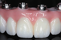
 |
 |
| Figure 21. Close-up image of the Prettau CAD/CAM Zirconia Bridge in patient’s mouth. | Figure 22. Patient with the Prettau CAD/CAM Zirconia Bridge. |
 |
 |
| Figure 23. Panoramic radiograph showing the Prettau Zirconia Implant Bridge. Note the radioopaque nature of the prosthesis. | Figure 24. Tissue side of the Prettau Zirconia Bridge, showing the convex cleansable) areas between interfaces. |
CASE REPORT
Diagnosis and Treatment Planning
A 47-year-old female in good health presented with multiple missing teeth. Her remaining maxillary and mandibular teeth had a questionable long-term prognosis. Her existing maxillary fixed bridge was mobile and was easily removed by the patient (Figure 9). She expressed that she did not want a removable option for tooth replacement, and desired a treatment option that required the shortest treatment time and least cost possible.
After proper diagnosis and review of findings, a treatment plan consisting of full-arch maxillary and mandibular screw-retained zirconia bridge (Prettau Zirconia [Zirconzahn USA]). After reviewing the initial CBCT scan with the patient, it was determined that an immediate maxillary denture would be utilized after extractions and implant placement to accommodate 2-stage healing. For the mandible, it was determined that a full-arch fixed-acrylic provisional supported by one natural molar tooth and one immediate loaded implant would be sufficient during the anticipated 4-month healing process. The plan met the needs and requirements of the patient and was accepted.
Presurgical workup included full-arch impressions, photographs, bite records, face-bow transfer, intraoral radiographs, and CBCT scan (iCAT [Imaging Sciences International]). An immediate maxillary denture and a mandibular metal reinforced provisional were created in advance of the planned surgical intervention.
Clinical Protocol: Surgery
After local anesthesia (5 carpules of Lidocaine HCL 2%/Epinephrine 1/100,000 [Cook Waite]) was administered, the remaining maxillary and mandibular teeth were removed, except for tooth No. 31. The CBCT was taken, postextraction. The scan data was imported into an interactive treatment planning software (Treatment Studio [Imaging Sciences International]), and implant receptor sites were planned for both arches with the restorative goal in mind. The scan data provided information with respect to the amount of potential alveolar reduction required to facilitate implant placement. The advance planning allowed for one surgical procedure, decreasing patient morbidity with a reduction of surgical procedures. Six implants were placed in the maxillary arch between the sinuses. Six implants were then placed in the mandibular symphysis region between the foramen with an adequate zone of safety from the inferior alveolar and mental nerves (Figure 10). It should be noted that the sixth implant in the mandible was initially placed to help support the mandibular fixed provisional, and would only be used for the definitive restoration if it remained fully integrated at the time of final impressions. Enough bone was removed to allow for 12 to 15 mm of prosthetic space in each arch, and to support 12-mm long implants.
Implants placed in the maxilla were positioned so that the screw access holes would be directed at the cingulum of the maxillary anterior teeth and through the occlusal envelope of the premolars. The distal most implants in the maxilla were tilted slightly distally to allow for a single tooth molar cantilever to maximize the A-P spread. The mandibular distal most implants were placed 3 mm from the mental foramen with a similar distal angulation to support a cantilevered first molar to maximize the A-P spread (Figure 11). The mandibular implants were also placed with a lingual angulation so that the screw access holes would be directed toward the lingual surface of the mandibular teeth. In the mandibular premolar areas, the screw access holes were directed toward the occlusal envelope. Mandibular alveolar bone reduction was accomplished to about half the depth of the extracted tooth sockets, allowing for 12 to 15 mm of prosthetic space required for the zirconia framework. The CBCT scan information in combination with clinical observation guided the parameters for surgical success, although a surgical guide was not used (Figure 12).
After maxillary implant placement cover screws were placed, the residual tooth socket areas were grafted with DFDBA putty and primary closure was obtained with 4-0 Vicryl (Ethicon) with continuous interlocking sutures. The immediate denture was then soft relined (COE-SOFT [GC America]) and delivered. Mandibular residual socket areas were grafted with DFDBA putty after implant placement and primary closure obtained except for the one anterior implant that was immediately loaded. Tooth No. 31 was prepared for a crown prior to surgery and a metal reinforced provisional was delivered, supported by tooth No. 31 and one anterior implant. Both the maxillary and mandibular implants were allowed to integrate for 4 months.
Second-Stage Implant Uncovering
After a healing time of 4 months, the maxillary and mandibular implants were uncovered. Utilizing a lingually placed crestal incision helped to preserve as much keratinized tissue as possible to wrap around the implants. Once all implants were uncovered for both maxillary and mandibular arches, the available keratinized tissue was repositioned toward the facial and securely sutured around the 3-mm titanium healing caps. It is recommended that shorter 3-mm healing collars are utilized so that the subsequent prosthetic try-in and delivery stages are not impeded by excess tissue. Surgical repositioning of the soft tissue at uncovering, gingivectomy, and/or periodontal plastic surgical techniques are often required at times to obtain this 3-mm healing collar limit. The soft tissue was then allowed to heal via secondary intention between the healing caps during a 3-week period (Figure 13).
Impressions, Indexing, and Verification
After a 3-week period following implant uncovering, adequate healing was observed. The healing collars were removed and open-tray impression transfer copings were placed on each implant. For both the maxillary and mandibular arches, the impression transfer copings were connected with a dental floss matrix and then layered with dual-cure resin (Figure 14). An open-tray impression was taken using a unique cellophane cover tray that contained the polyether impression material. An indexed impression for the maxilla was taken utilizing a bite registration material inside the wax duplicate denture (Figure 15). A special wax bite rim was fabricated for the mandibular right first molar before it was extracted. The mandibular wax rim was adjusted to the appropriate vertical dimension, lip support, and was then indexed to the implants. These indices were then used to relate the bite registration and correct intraoral position of the prosthesis to the articulator. The articulated models based on the index allowed for a screw-retained acrylic provisional to be fabricated. From the master model the laboratory created a rigid verification jig made from a heated acrylic rod and powder and liquid acrylic (Figure 16). A panoramic radiograph verified seating of the maxillary and mandibular verification jigs (Figure 17). An acrylic processed screw-retained provisional was fabricated for the maxillary and mandibular arches and then delivered to the patient (Figure 18). These screw-retained provisionals aided the clinician to “test drive” the occlusion, phonetics, midline, etc, on the patient. The patient wore the screw-retained acrylic provisionals for 3 weeks (Figure 19). The previous immediate dentures and wax duplicate guided the formation of the polymethylmethacrylate (PMMA) provisional prosthesis.
Final Zirconia Prosthesis Creation and Delivery
Once the doctor and patient approve the PMMA screw-retained provisional, it is then used as a fabrication guide for the final zirconia screw-retained prosthesis. The PMMA is then scanned in a high-resolution optical scanner and saved as an stereolithography (STL) CAD file before being sent back to the doctor (Figure 20). Once the doctor approves the PMMA provisional, it is duplicated by the laboratory into a CAD/CAM milled final zirconia prosthesis from the STL file. If the doctor makes changes to the PMMA during the try-in with the patient, then an impression is taken of the changes intraorally. The dental laboratory can combine the changes with the previous original STL file after scanning the modified model. The final zirconia prosthesis is then delivered to the patient and the prosthesis screws are torqued down and covered with composite (Figures 21 and 22). A final panoramic radiograph verifies seating (Figure 23). Titanium abutments are bonded into the underside of the final zirconia prosthesis as the interface between the implants and the prosthesis. The underside of the prosthesis is convexly shaped between the interfaces to allow for improved hygiene (Figure 24). One advantage of zirconia is that the screw holes blend in aesthetically due to a lack of bar structure underneath. Moreover, screw-retained zirconia bridges are stronger than acrylic or porcelain prosthetics.
IN SUMMARY
This article has described the rationale, science, treatment planning, surgical, prosthetic, and laboratory steps necessary to create screw-retained implant-supported zirconia prostheses. Presurgical prosthetic planning combining conventional prosthetic protocols with CBCT imaging, diagnosis, and treatment planning can allow for adequate cantilevered occlusion without additional grafting in many cases.
Advantages of zirconia as an implant-supported prosthetic material have been shown. These advantages include: lack of casting distortion due to the CAD/CAM process; highly reduced chance of chipping compared to acrylic or porcelain; reduction in required intra-arch space for prosthesis design; and stronger and improved aesthetics of screw access hole areas. The early stages of a denture fabrication and duplicate wax-up provided the foundation for the subsequent procedural steps for prosthetic success with monolithic zirconia. Combined technological advances in the CAD/CAM process, and the specific zirconia material utilized, demonstrated that the parameters of prosthetic success could be clinically tested when the patient wore an acrylic screw-retained version of what would then become the final product.
A full-arch implant-supported zirconia screw-retained prosthesis offers many advantages over alternative prosthetic options.
References
- Ganz SD. Techniques for the use of CT imaging for the fabrication of surgical guides. Atlas Oral Maxillofac Surg Clin North Am. 2006;14:75-97.
- Tischler M, Ganz SD. The CT/CBCT-based team approach to care. Part I: Identifying the implant patient and prosthetic options. Dent Today. 2012;31:74-79.
- Tischler M, Ganz SD. The CT/CBCT-based team approach to care: Part 2: Communication with the surgeon to support the final prosthesis. Dent Today. 2012;31:108-115.
- Tischler M, Ganz SD. The CT/CBCT-based team approach to care. Part 3: Identifying prosthetic options through team communication. Dent Today. 2012;31:56-63.
- Abu-Saleh T, Marnewick J. Implant-supported crowns for a shortened dental arch: a case report. J Contemp Dent Pract. 2008;9:114-121.
- Witter DJ, Van Elteren P, Käyser AF, et al. Oral comfort in shortened dental arches. J Oral Rehabil. 1990;17:137-143.
- Tischler M. A maxillary fixed bridge supported by dental implants: treatment sequence and soft-tissue considerations. Compend Contin Educ Dent. 2012;33:340-344.
- Kanno T, Carlsson GE. A review of the shortened dental arch concept focusing on the work by the Käyser/Nijmegen group. J Oral Rehabil. 2006;33:850-862.
- Wu YQ, Huang W, Zhang ZY, et al. Tilted implants treatment without maxillary sinus grafting in severely resorbed posterior maxilla [in Chinese]. Shanghai Kou Qiang Yi Xue. 2011;20:506-511.
- Maló P, de Araújo Nobre M, Lopes A, et al. “All-on-4” immediate-function concept for completely edentulous maxillae: a clinical report on the medium (3 years) and long-term (5 years) outcomes. Clin Implant Dent Relat Res. 2012;14(suppl 1):e139-e150.
- Zampelis A, Rangert B, Heijl L. Tilting of splinted implants for improved prosthodontic support: a two-dimensional finite element analysis. J Prosthet Dent. 2007;97(suppl 6):S35-S43.
- Brosky ME, Korioth TW, Hodges J. The anterior cantilever in the implant-supported screw-retained mandibular prosthesis. J Prosthet Dent. 2003;89:244-249.
- Misch C. Classifications and treatment options of the completely edentulous arch in implant dentistry. Dent Today. 1990;9:26-30.
- Zitzmann NU, Marinello CP. Implant-supported removable overdentures in the edentulous maxilla: clinical and technical aspects. Int J Prosthodont. 1999;12:385-390.
- Rosenbaum N. Full-arch implant-retained prosthetics in general dental practice. Dent Update. 2012;39:108-116.
- Shor A, Shor K, Goto Y. Implant-retained overdenture design for the malpositioned mandibular implants. Compend Contin Educ Dent. 2006;27:411-421.
- Yilmaz B, Seidt JD, McGlumphy EA, et al. Comparison of strains for splinted and nonsplinted screw-retained prostheses on short implants. Int J Oral Maxillofac Implants. 2011;26:1176-1182.
- Chaar MS, Att W, Strub JR. Prosthetic outcome of cement-retained implant-supported fixed dental restorations: a systematic review. J Oral Rehabil. 2011;38:697-711.
- Karl M, Taylor TD, Wichmann MG, et al. In vivo stress behavior in cemented and screw-retained five-unit implant FPDs. J Prosthodont. 2006;15:20-24.
- Shadid R, Sadaqa N. A comparison between screw- and cement-retained implant prostheses. A literature review. J Oral Implantol. 2012;38:298-307.
- Misch CE. Dental Implant Prosthetics. St. Louis, MO: Elsevier Mosby; 2005:49#.
- Purcell BA, McGlumphy EA, Holloway JA, et al. Prosthetic complications in mandibular metal-resin implant-fixed complete dental prostheses: a 5- to 9-year analysis. Int J Oral Maxillofac Implants. 2008;23:847-857.
- Rothfuss LG, Hokett SD, Hondrum SO, et al. Resin to metal bond strengths using two commercial systems. J Prosthet Dent. 1998;79:270-272.
- Taira Y, Matsumura H, Yoshida K, et al. Influence of surface oxidation of titanium on adhesion. J Dent. 1998;26:69-73.
- Tan KB. The clinical significance of distortion in implant prosthodontics: is there such a thing as passive fit? Ann Acad Med Singapore. 1995;24:138-157.
- Castellani D, Baccetti T, Clauser C, et al. Thermal distortion of different materials in crown construction. J Prosthet Dent. 1994;72:360-366.
- De Vasconcellos DK, Özcan M, Maziero Volpato CÂ, et al. Strain gauge analysis of the effect of porcelain firing simulation on the prosthetic misfit of implant-supported frameworks. Implant Dent. 2012;21:225-229.
- Al-Omari WM, Shadid R, Abu-Naba’a L, et al. Porcelain fracture resistance of screw-retained, cement-retained, and screw-cement-retained implant-supported metal ceramic posterior crowns. J Prosthodont. 2010;19:263-273.
- Karl M, Holst S. Strain development of screw-retained implant-supported fixed restorations: Procera implant bridge versus conventionally cast restorations. Int J Prosthodont. 2012;25:166-169.
- Papaspyridakos P, Benic GI, Hogsett VL, et al. Accuracy of implant casts generated with splinted and non-splinted impression techniques for edentulous patients: an optical scanning study. Clin Oral Implants Res. 2012;23:676-681.
- Sannino G, Pozzi A, Schiavetti R, et al. Stress distribution on a three-unit implant-supported zirconia framework. A 3D finite element analysis and fatigue test. Oral Implantol (Rome). 2012;5:11-20.
- Jung YS, Lee JW, Choi YJ, et al. A study on the in-vitro wear of the natural tooth structure by opposing zirconia or dental porcelain. J Adv Prosthodont. 2010;2:111-115.
- Kim MJ, Oh SH, Kim JH, et al. Wear evaluation of the human enamel opposing different Y-TZP dental ceramics and other porcelains. J Dent. 2012;40:979-988.
- Correia A, Fernandes J, Campos J, et al. Stress analysis of cantilever-fixed partial denture connector design using the finite element method. Rev Odonto Ciênc. 2009;24:420-425.
- Rojas-Vizcaya F. Full zirconia fixed detachable implant-retained restorations manufactured from monolithic zirconia: clinical report after two years in service. J Prosthodont. 2011;20:570-576.
- Oliva J, Oliva X, Oliva JD. All-on-three delayed implant loading concept for the completely edentulous maxilla and mandible: a retrospective 5-year follow-up study. Int J Oral Maxillofac Implants. 2012;27:1584-1592.
Dr. Tischler is a general dentist in private practice in Woodstock, NY. He is a Diplomate of the American Board of Oral Implantology Implant Dentistry, a Diplomate and Fellow of the International Congress of Oral Implantologists, a Fellow of the American Academy of Implant Dentistry, and a Fellow and graduate of the Misch International Institute. He is on the CE editorial board for Dentistry Today and on the editorial advisory board for the Journal of Implant and Advanced Clinical Dentistry. He has published many articles in various dental journals and lectures internationally on the principles of implant dentistry and bone grafting. He is the director of the dental implant department for Tischler Dental Laboratory and is also on the BioHorizons educational speakers’ panel. He offers in-office courses at his teaching facility in Woodstock many times during the year and has a popular instructional DVD available that covers the principles of implant dentistry and bone grafting. He can be reached at (845) 679-3706 or at tischlerdental.com.
Disclosure: Dr. Tischler is the owner of Tischler Dental Laboratory, which produces the Prettau Implant Bridge.
Dr. Ganz graduated from the University of Medicine and Dentistry of New Jersey (UMDNJ) Dental School, and then completed a 3-year specialty program in maxillofacial prosthetics at MD Anderson Cancer Center in Houston, Tex. Dr. Ganz is a Fellow of the Academy of Osseointegration, Diplomate and member of the Board of Directors of the International Congress of Oral Implantologists, is on staff at Hackensack University Medical Center, and is on faculty at UMDNJ Dental School. He maintains a private practice for prosthodontics, maxillofacial prosthetics, and implant dentistry in Fort Lee, NJ. He currently serves as associate editor for the peer-reviewed journal Implant Dentistry and is on the editorial staff of many other publications. He has more than 70 publications in various professional journals and has contributed to numerous scientific textbook chapters. Dr. Ganz’s book, An Illustrated Guide to Understanding Dental Implants, has been a classic for patient education for more than 19 years. Dr. Ganz regularly presents internationally on the prosthetic and surgical phases of implant dentistry, and is considered one of the world’s leading experts in the field of computer utilization for 3-dimensional diagnostics and treatment planning applications. He can be reached at (201) 592-8888, at sdgimplant@aol.com, or at drganz.com.
Disclosure: Dr. Ganz reports no disclosures.
Dr. Patch is a general dental practitioner in Woodstock, NY. In 2009, Dr. Patch received her DMD degree from the University of Connecticut School of Dental Medicine, where she received various awards including the American Academy of Esthetic Dentistry Merit Award. Together with Dr. Tischler, Dr. Patch is part of the Prettau Implant Bridge team, performing the restorative aspects of the process. Additionally, Dr. Patch is a continuing education lecturer on the restorative components of the Prettau Implant Bridge. In 2012, she was selected as one of Dental Products Report’s Top 25 Women in Dentistry. She can be reached at claudia@tischlerdental.com.
Disclosure: Dr. Patch reports no disclosures.


