

One of the most difficult challenges we have in clinical practice is creating one or more crowns to fit under an existing clasp removable partial denture. A multitude of techniques have been described to perform this procedure. Direct methods, indirect methods, and combination techniques of both have been developed and published in the dental literature. The fact that so many different techniques have been described points to the difficulty of retrofitting a crown(s) to fit under a clasp partial denture. It can be a truly daunting task.
Ideally, a removable partial denture is made after the necessary crown(s) is placed on the tooth supporting the partial denture. However, a patient may present with an existing removable partial denture that fits well but also has an abutment tooth or multiple abutment teeth that are carious and not restorable unless crowned. Another scenario is that the patient may have one or more abutments with porcelain-fused-to-metal crowns and fractured porcelain, necessitating replacement of the crown(s). The contour of the new crown(s) must allow the partial denture to be placed with its pre-existing path of insertion. The crown contours must also provide the appropriate undercuts for the clasps on the partial denture in order to engage the crown(s) with some retention. If multiple crowns have fractured porcelain, the task of retrofitting is greatly magnified.
The relationship between the removable partial denture and the prepared teeth is critical. Capturing that relationship accurately in an impression can be difficult. In addition, many steps in crown fabrication have inherent dimensional changes in the materials used. From the setting of impression material, pouring of lab models, waxing and investing for casting, and finally, to baking on porcelain, it’s a wonder that porcelain-fused-to-metal-crowns are as predictable and successful as they usually are.
It is not the purpose of this article to provide an in-depth review of all the techniques that have been discussed in the past, but rather the purpose is to present a technique that is predictable and efficient for addressing the challenge in daily practice of retrofitting a crown(s) under an existing clasp removable partial denture. Elements of many previous techniques are included in the method being presented in this article, and for that reason, a very brief historical perspective will be provided.
BACKGROUND
Among the various techniques to accomplish this task is a direct technique that develops a resin and wax crown pattern intraorally. This was proposed by Killebrew1 in 1961. A variation of this technique was introduced in 1963 by Ewing,2 when he substituted a prefabricated cadmium crown form that was refined intraorally with the partial denture in the mouth. The obvious advantage of a direct technique is that the patient doesn’t have to be without his or her partial while the crown is being made. The major disadvantage to a direct technique is increased chair time. It is also much harder to create proper contour of the crown form while working in the mouth as compared to out of the mouth. Therefore, there is a greater potential for inaccuracies in the end result using a direct technique.
Indirect techniques have been presented by Barrett and Pilling3 in 1965, McArthur4 in 1984, Goldberg and Jones5 in 1976, Hill6 in 1977, and Raskin7 in 1983. All of these techniques offer the advantages of letting a patient keep his or her partial until the crown is completed; they also allow better access and visibility for fabrication of the crown.
The merging of direct and indirect techniques arose as attempts were made to accomplish this challenging task better. Combination techniques were described by Thurgood, Thayer, and Lee8 in 1973, Welsh9 in 1975, and Gavelis10 in 1981. Other authors who have published articles on combination techniques are Sigaroudi11 (1985), Lubovich and Peterson12 (1977), Loft, Reynolds, and Lundquist13 (1977), and Jordan, et al14 (1982). No single technique has appeared to emerge as the best way to retrofit a crown predictably and consistently to a removable clasp partial denture.
In this article a method will be described that includes both direct and indirect steps. The author has been able to perform this procedure many times with either minimal or no adjustment to the new crown(s) made to fit under an existing clasp partial.
DIAGNOSIS
 |
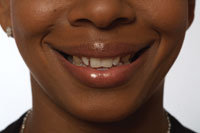
| Figure 1. Preoperative view. |
The patient presented with an existing lower removable partial denture. The partial was functional, and she had no desire to replace it. She reported “some sensitivity in teeth on the bottom right.” On clinical examination, it was clear she had defective amalgam restorations in teeth Nos. 29 and 30. Figure 1 shows the large mesio-occlusal amalgam restoration separating from tooth No. 30 on both the occlusal and mesial aspects. Tooth No. 30 also had an extensive facial amalgam restoration that had outlived its usefulness (Figure 1). It was also evident that tooth No. 29 had a history of extensive restoration and facial enamel that had already begun to crack (Figure 1).
The existing partial denture had a clasp and rest assembly that used teeth Nos. 29 and 30 for support on the right side. Radiographs revealed possibile endodontic treatment needed on No. 29.
TREATMENT PLAN
The treatment plan was to fabricate splinted porcelain-fused-to-metal-crowns for teeth Nos. 29 and 30. The sequence of treatment was planned as follows:
(1) full-contour preoperative impression
(2) removal of old amalgams and recurrent caries
(3) endodontic treatment if necessary
(4) placement of post and/or cores as needed
(5) preparation, impressioning
(6) creating and cementing temporaries to allow patient to function with existing partial
(7) creation of transfer copings
(8) luting of removable partial to transfer copings in occlusion
(9) fabrication of splinted porcelain-fused-to-gold crowns
(10) fitting and cementation of crowns.
Note: The crowns would be splinted because the upright and rests of the partial were located between teeth Nos. 29 and 30. This is where the most pressure would occur in function, and splinting the crowns would assure maximum resistance to displacement as well as the best chance for success.
CHAIRSIDE PROCEDURE
A full-contour preoperative impression is needed for fabricating the temporary crowns to ensure that they will fit under the partial denture. It has been the author’s experience that any other technique to make temporaries is usually accompanied by a large amount of chair time spent adjusting their contour and occlusion. In addition, when the removable partial denture is placed in the mouth or removed, it will tend to dislodge the temporaries if the contours do not coincide with a proper survey line for insertion and removal. Using a full-contour preoperative impression will ensure that minimal to no adjustments are necessary, because the temporaries will have the same contours as the teeth they are covering prior to preparation.
 |
 |
| Figure 2. Adding Gradia flowable composite to margin before full-contour preoperative impression. | Figure 3. Making full-contour preoperative impression. |
Before making the preoperative impression and without etching the tooth, Gradia Flo flowable composite (GC America) was added to the exposed root areas on tooth No. 30 (Figure 2) and cured with a Demetron Optilux 501 halogen curing light (Sybron Kerr). This was done to provide a thicker marginal area in the temporary crown so that the material used for the temporaries would not fracture off. When this marginal area is too thin, it can easily break off on either cementation or removal of the temporaries. A Triple Tray (Premier USA) with Position Penta Quick (3M ESPE) was placed between upper and lower right quadrants, and the patient was instructed to close her teeth (Figure 3). In order to achieve proper occlusion in the temporaries, it is essential that the patient closes into his or her usual occlusion. This can be difficult for some patients because they are numb from local anesthesia or they pay too much attention to the presence of the impression tray. To ensure that closure is in a patient’s usual occlusion, I ask the patient to “close so that your teeth on the opposite side close normally.” By having the opposite teeth close normally, you ensure that the side that has the tray on it also closes normally.
 |
 |
| Figure 4. Post cemented in place. | Figure 5. Core buildup. |
 |
| Figure 6. Packing retraction cord. |
Root canal therapy was initiated on tooth No. 29 using the Elements apex locator (SybronEndo) for canal measurement, and the canals were instrumented with Premier K-Files (Premier Dental) and RC-Prep (Premier Dental). The canal was sealed with Ketac Endo (3M ESPE) and gutta-percha points (DENTSPLY Maillefer). Using a total-etch technique, an Integra Post (Premier USA) was cemented (Figure 4). The post space was etched with Ultra-Etch (Ultradent), rinsed, and dried with paper points. Then a thin layer of Clearfil Photo Bond adhesive (Kuraray Dental) was applied. A gentle stream of air was directed into the post space to evaporate excess solvent in the adhesive. Integra Cem (Premier USA) was mixed and placed onto the post, and the post was inserted. A 2- to 3-second light cure set the surface layer of the Integra Cem and prevented movement of the post as the core was built. CosmeCore (Cosmedent) was used to build up the core on tooth No. 29. The material was injected in the Flow-Thru post head and around the post, then light cured for 40 seconds (Figure 5). Preparations were completed, and Ultrapak No. 00 retraction cord (Ultradent) with Astringedent (Ultradent) on it was placed using the Fischer Cord Packer (Ultradent, Figure 6) after achieving hemostasis using Visco-stat Wintergreen (Ultradent) applied with a Dento-Infusor (Ultradent).
 |
| Figure 7. Final impression. |
The working impression for the crowns was made using Impregum Penta Soft Medium Body (3M ESPE) in a Wide Body Posterior Triple Tray (Premier USA), and Permadyne Garant 2:1 (3M ESPE) was injected into the sulci. All the marginal areas were captured in the impression (Figure 7), and it was sent to the laboratory with a prescription for transfer copings with retention balls on the facial and lingual surfaces.
 |
 |
| Figure 8. Connect fiber. | Figure 9. Temporaries in place with partial seated over them. |
Temporary crowns were made using Luxatemp Fluorescence (Zenith/DMG) and 2-mm Connect fiber (Sybron Kerr, Figure 8) for reinforcement. After lubricating the preparations with a thin layer of mineral oil, Luxatemp Fluorescence was injected into the preoperative impression about halfway, and the fiber was inserted and then covered with additional Luxatemp. Since the temporaries had to withstand the occlusal pressure of the partial denture rests in function, there was the distinct possibility of the splinted temporary crowns splitting apart from each other. The fiber would keep them in place even if the crowns should separate. Figure 9 shows the temporary crowns in place under the removable partial denture.
 |
 |
| Figure 10. Resin transfer copings. | Figure 11. Transfer copings luted to removable partial. |
 |
 |
| Figure 12. Pickup impression. | Figure 13. Splinted crowns. |
The transfer copings (Figure 10) were returned from the laboratory. Their marginal fit was confirmed, and they were luted to the removable partial denture with the patient biting down in occlusion. GC Pattern Resin (GC America) was used to connect the partial and copings (Figure 11). It is critical to have the patient close in occlusion so that the final contours and occlusion will account for the functional position of the partial in the contour of the crowns. A full-arch impression was made to pick up the removable partial and luted copings so that a working model could be poured. Figure 12 shows the Flexitime (Heraeus Kulzer) pickup impression with the luted copings. Bite registration, an impression of the opposing arch, and a shade were sent to the lab for the final crowns. The final restorations (Figure 13) were splinted for the same reason the temporaries were, namely to withstand the downward force of the partial’s rests in function.
 |
 |
| Figure 14. Crowns on model. | Figure 15. Checking contact area. |
 |
 |
| Figure 16. Adjusting contact area. | Figure 17. Vaseline on removable partial frame. |
 |
 |
| Figure 18. Cementing crowns. | Figure 19. Cleaning interproximal area. |
 |
| Figure 20. Completed case in patient’s mouth. |
The crowns and partial were returned on a full-arch model (Figure 14). When trying the crowns in without the partial, they did not seat all the way. Using floss to check the contact areas, it was clear that the distal contact area was slightly overbuilt. Bausch Extra Thin 40-µm articulating paper (Pulpdent) was used to ascertain where the binding occured (Figure 15). The contact area was adjusted using a Brasseler ET9 finishing diamond (Brasseler USA, Figure 16) and repolished with NTI polishers (Axis Dental). Prior to cementation of the crowns, the partial was heavily lubricated with Vaseline so that the cement would not stick to it (Figure 17). Fuji Plus cement (GC America) was mixed and injected into the crowns. After isolation with cotton rolls and gentle air drying, the crowns were seated, and the partial was placed in the patient’s mouth (Figure 18). The patient was asked to bite down hard and stay closed. This was done to ensure that the crowns were seated all the way with the partial in function.
To minimize the cleanup phase, the excess cement was removed in the gel stage, prior to complete setting. Using GUM Eez-Thru Floss Threaders (Sunstar J. Butler), the interproximal area between teeth Nos. 29 and 30 was cleaned of all excess cement (Figure 19). The nearby contact areas were flossed as well. Figure 20 shows an occlusal view of the crowns and partial in place.
CONCLUSION
A rationale and technique have been offered for one of the most difficult tasks we have to perform in clinical practice. It is my hope that the information and technique in this article answer this challenge in a way that minimizes adjustments and leads to consistent and predictable success.
References
1. Killebrew RH. Crown construction for broken down partial denture abutments. J Prosthet Dent. 1961;11:93-94.
2. Ewing JE. Direct metal pattern technique for full-crown restorations. J Am Dent Assoc. 1963;67:822-826.
3. Barrett DA, Pilling LO. The restoration of carious clasp-bearing teeth. J Prosthet Dent. 1965;15:309-311.
4. McArthur DR. Fabrication of full coverage restorations for existing removable partial dentures. J Prosthet Dent. 1984;51:574-576.
5. Goldberg AT, Jones RD. Constructing cast crowns to fit existing removable partial denture clasps. J Prosthet Dent. 1976;36:382-386.
6. Hill GM. Construction of a crown to fit a removable partial denture clasp. J Prosthet Dent. 1977;38:226-228.
7. Raskin ER. An indirect technique for fabricating a crown under an existing clasp. J Prosthet Dent. 1983;50:580-581.
8. Thurgood BW, Thayer KE, Lee RE. Complete crowns constructed for an existing partial denture. J Prosthet Dent. 1973;29:507-512.
9. Welsh SL. Complete crown construction for a clasp-bearing abutment. J Prosthet Dent. 1975;34:320-323.
10. Gavelis JR. Fabricating crowns to fit clasp-bearing abutment teeth. J Prosthet Dent. 1981;46:673-675.
11. Sigaroudi K. Restoring abutment teeth with cast restorations to fit existing removable partial dentures. J Prosthet Dent. 1985;53:628-631.
12. Lubovich RP, Peterson T. The fabrication of a ceramic-metal crown to fit an existing removable partial denture clasp. J Prosthet Dent. 1977;37:610-614.
13. Loft GH, Reynolds JM, Lundquist DO. An indirect-direct method of crown fabrication for existing removable partial denture clasps. J Prosthet Dent. 1977;38:589-591.
14. Jordan RD, Turner KA, Taylor TD. Multiple crowns fabricated for an existing removable partial denture. J Prosthet Dent. 1982;48:102-105.
Acknowledgment
Thanks to Robert Renza, MDT, in New City, NY, for his assistance with this case. Images in this article were photographed with the Kodak Easy Share 6490 Dental Camera.
Dr. Fier is a full-time practicing clinician and lectures in the United States and internationally on aesthetic and restorative dentistry. He is the executive vice president of the American Society for Dental Aesthetics, a diplomate of the American Board of Aesthetic Dentistry, and a fellow of the American Society for Dental Aesthetics, the American College of Dentists, the International College of Dentists, the Academy for Dental-Facial Esthetics, and the Academy of Dentistry International. Dr. Fier has been a consultant to the ADA on patient education materials and has appeared on the cable television series Feeling Good. He has served as an adjunct professor at the dental schools of NYU, UCLA, University of Minnesota, and Loma Linda, and is a contributing editor for Reality and Dentistry Today. For the past 5 years he has been listed in Dentistry Today’s annual list of Leaders in Continuing Education. He may be reached at (845) 354-4300 or docmarv@optonline.net.
Disclosure: From time to time, the author receives material and lecture support from many of the companies mentioned in this article.