


INTRODUCTION
Yes, dentists need dental work too. Those who have the honor and privilege of providing care for a colleague should understand that there are certain special conditions associated with the endeavor. A dentist brings him- or herself to another dentist with a high degree of confidence in that practitioner but usually needs to express him- or herself about the treatment process and should be “heard” with a different perspective than that of a non-dentist patient.
Expect to allow extra office time for the discussion of details. The dentist/patient may have certain expectations about procedural protocols, materials, case design, and even follow-up professional monitoring and maintenance. After the above discussion, written agreements should be prepared for signed consent that include the right of the treating dentist to have the final say on critical issues like materials, case design, dental laboratory choice, etc.
The dentist/patient who is the subject of this article has been a friend of the author for 40-plus years prior to coming in for care. Both the dentist/patient and the author had been part-time teachers at the University of Pennsylvania School of Dental Medicine for all of those years. The dentist/patient has also been a valued member of the author’s private dental study club since its inception in 2004. This relationship and background information was quite helpful to the author in formulating the vision for the dentist/patient’s new smile display.
CASE REPORT
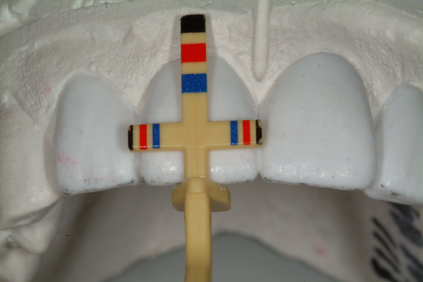
The dentist/patient was a 74-year-old male at the time of treatment presentation (Figures 1 and 2). The dento-facial examination revealed a slight dental midline (DM) to facial midline (FM) discrepancy, a visually apparent dental vertical (DV) axis to facial vertical (FV) axis disharmony, and noticeable dental horizontal (DH) to facial horizontal (FH) incisal edge position irregularities.1 The DM to FM assessment is accomplished using a 10- to 12-in-long piece of dental floss held vertically by the operator in trial position and with the patient viewing/approving this location by looking into a large handheld mirror at arm’s length.2 The agreed FM position of the dental floss also determines DV to FV and DH to FH relationships.3
 |
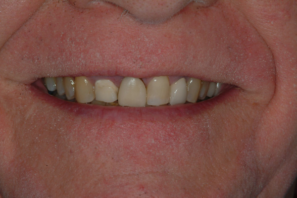 |
| Figure 1 Dentist/patient in full smile at presentation. | Figure 2 Full smile, lower one-third of face at presentation. |
 |
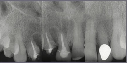 |
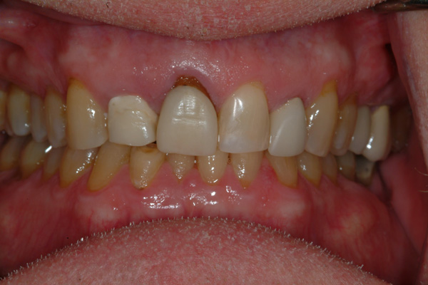
| Figure 3 Retracted dentition at presentation. | Figure 4 Radiographic images of the maxillary anterior teeth at presentation. |
The central and lateral incisors were not symmetrical to each other in width or length and did not have an equidistant relationship to the superior contour edge of the lower lip. The dentist/patient had a normal or average lip-line smile display,4,5 but there were gingival swellings and irregular horizontal asymmetries of the gingival margin heights, which made for an unattractive presentation. There were existing full-coverage restorations on both lateral incisors and the right central incisor (Figure 3). The radiographic images made at presentation showed shortened clinical root lengths of both right incisors where endodontics and a number of periapical surgical procedures were previously performed (Figure 4). The periodontal mobility of both right incisors was 1+ degree; the left incisors measured zero mobility. There were 4-mm-deep probings at the mesiolabial of the right lateral incisor and the distolabial of the right central incisor. All other periodontal probings were 3 mm or less.
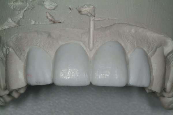
The dentist/patient and the dentist/operator agreed that the treatment plan should include correction of the above-described disharmonies and malpositions as well as correction of the uneven gingival margin display as a part of some periodontal therapy. A Facial Plane Relator device (Ho Dental Company) would be employed to find and measure the midline, vertical, and horizontal alignment disparities and transfer that information to the dental laboratory where the Chu’s Aesthetic Gauges (Hu-Friedy) would also be used to guide the design wax-up to biometric proportions6 (Figures 5 and 6).
 |
 |
| Figure 5 Laboratory design wax-up (Natural Esthetics Dental Laboratory, Blue Bell, Pa). | Figure 6 Image showing a 78% width-to-length proportion for the right central incisor, verified with the Esthetic Gauge (Hu-Friedy). |
 |
 |
| Figure 7 Splinted fixed provisional restorations on the 4 maxillary incisors, retracted view. | Figure 8 Splinted fixed provisional restorations on the 4 maxillary incisors, smile view. Some dental contour modifications were needed, but the overall parameters of facial midline to dental midline, facial vertical to dental vertical, and facial horizontal to dental horizontal had been satisfied. |
The proposed treatment plan started with scaling, root planing, coaching in personal daily plaque/biofilm control, and aesthetic crown-lengthening surgery with a soft-tissue laser (BIOLASE ezlase 940 Dental Laser [BIOLASE]). After some soft-tissue healing, and unbeknownst to the author, the dentist/patient decided to add acrylic to the newly exposed cervical areas of the right lateral and central incisors. This may have negatively impacted the short-term gingival healing of the right lateral incisor, retarding final healing, and the re-establishment of biological width dimensions.7 Full-coverage, splinted methyl methacrylate (Jet Acrylic [Lang Dental Manufacturing]) provisional restorations were later placed on the 4 incisors (Figures 7 and 8).
There was some discussion with the dentist/patient about splinted vs non-splinted restorations. The author’s position for splinted restorations won out based mainly on the compromised crown-to-root ratio of the right lateral and central incisors. No bone was removed during the periodontal surgical treatment.
 |
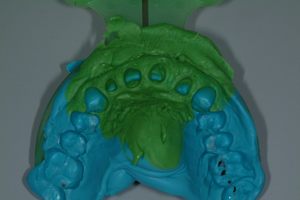 |
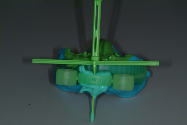
| Figure 9 The impression, bite registration, opposing dentition, and facial plane relationships (3) were captured with the Harmony Tray (Ho Dental Company). | Figure 10 Impression capture. |
 |
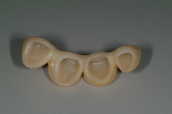 |
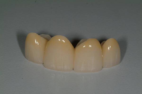
| Figure 11 Final 4-unit fixed porcelain-fused-to-zirconia prosthesis (Natural Esthetics Dental Laboratory). | Figure 12 Intaglio view. |
The final impressions were made with a vinyl polysiloxane dental impression material (Vaccu-sil [Ho Dental Company]) and a Harmony Tray (Ho Dental Company), which is designed to capture the tooth preparations, adjacent structures, opposing dentition, and bite relationship and also includes a Facial Plane Relator device mounted to the tray (Figures 9 and 10). A framework fitting and bisque bake try-in of the 4-unit splinted porcelain-fused-to-zirconia fixed prosthesis were performed, and contour and color modifications were made. The final prosthesis prior to placement is shown in Figures 11 and 12.
 |
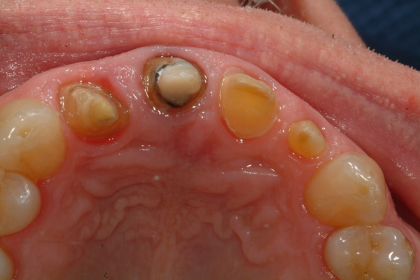 |
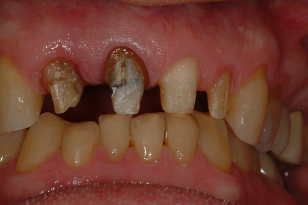
| Figure 13 Final tooth preparations prior to final case insertion/cementation, labial view. | Figure 14 Final tooth preparations prior to case insertion/cementation, incisal view. |
 |
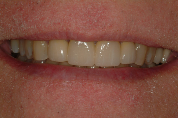 |
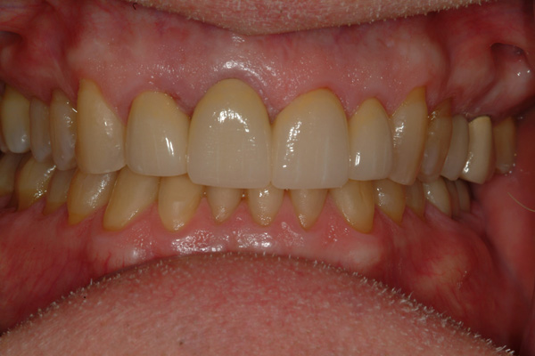
| Figure 15 Final restoration at the 1-month recall, retracted view. | Figure 16 Final restoration close-up smile view at the 1-month recall. |
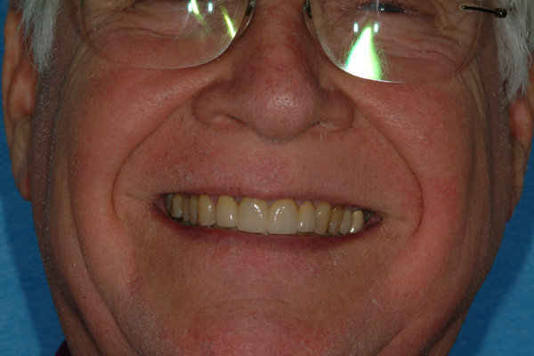
Figure 17 Final restoration full-face smile view at the 1-month recall.
The final preparations at final insertion still show some delayed gingival healing at the mesiolabial margin of the right lateral incisor, but not enough to prevent cementation of the final prosthesis (PANAVIA SA [Kuraray Noritake]) (Figures 13 and 14). Both dentist/patient and dentist/operator were pleased with the final restoration and new smile display (Figures 15 to 17).
CONCLUSION
A new smile display was fabricated for a dentist/patient. The main component was a 4-unit splinted fixed dental prosthesis. Setting the stage for this restoration included careful measurements and analyses of facial-to-dental relationships and modifications to adjacent local structures. Science-based dental measuring devices used by the dentist and dental laboratory were key to this predictable outcome.F
ACKNOWLEDGEMENT
The author wishes to thank Natural Esthetics Dental Laboratory in Blue Bell, Pa, for the fine technical work in fabricating the restoration shown in this article.
REFERENCES
1. Greenberg JR, Ho PP. Communicating facial plane information to the dental laboratory: introducing the Facial Plane Relator device. J Prosthet Dent. 2001;86:173-176.
2. Christensen GJ. Ask Dr. Christensen. Dental Economics. February 1, 2012. Accessed April 24, 2020. https://www.dentaleconomics.com/science-tech/periodontics-and-oral-surgery/article/16392360/ask-dr-christensen
3. Greenberg JR, Bogert MC. A dental esthetic checklist for treatment planning in esthetic dentistry. Compend Contin Educ Dent. 2010;31:630-638.
4. Bhuvaneswaran M. Principles of smile design. J Conserv Dent. 2010;13:225-232.
5. Manjula WS, Sukumar MR, Kishorekumar S, et al. Smile: a review. J Pharm Bioallied Sci. 2015;7(suppl 1):S271-S275.
6. Orozco-Varo A, Arroyo-Cruz G, Martínez-de-Fuentes R, et al. Biometric analysis of the clinical crown and the width/length ratio in the maxillary anterior region. J Prosthet Dent. 2015;113:565-570.e2.
7. Ingber JS, Rose LF, Coslet JG. The “biologic width”–a concept in periodontics and restorative dentistry. Alpha Omegan. 1977;70(3):62-5.
ABOUT THE AUTHOR
Dr. Greenberg is a clinical professor of restorative dentistry at the Temple University Maurice H. Kornberg School of Dentistry and a retired clinical professor of periodontics at the University of Pennsylvania School of Dental Medicine. He is in private practice in Villanova, Pa. He can be reached at the website createbeautifulsmiles.com.
Disclosure: Dr. Greenberg is the inventor of the Facial Plane Relator and is a non-paid consultant for Ho Dental Company, LLC.
RELATED ARTICLES
Polishing Techniques for Beauty and Longevity
Age Grouping to Optimize Augmentation Success
Subcision for Lip and Perioral Scarring Cosmesis: Case Report


