

Our patients present to our practices requesting consultations on various options for replacing missing teeth in edentulous spaces. As was discussed in the first installment of the diagnosis and surgical protocol article titled “Proper Preparation for Prosthetically Driven Dental Implants: CBCT Diagnosing and Surgical Protocol” (June 2017), our patient had a strong desire to have some teeth placed permanently in his maxillary anterior area. We decided on a screw-retained implant bridge designed from the maxillary right cuspid area to the left first bicuspid site. Other options considered included the fabrication of a new conventional maxillary removable partial denture. However, because the patient had been wearing a removable partial denture since he lost his teeth in a motorcycle accident years ago, he was not interested in this option. Fewer implants could be strategically placed, and an implant-retained removable appliance could be made. Again, our patient requested a permanent solution to improve chewing function, aesthetics, and quality of life.
Designing the Aesthetic Outcome Prior to Any Surgical Intervention
The ability to design our aesthetic crown and bridgework using CAD/CAM software is a wonderful advancement. We can now virtually design the final aesthetic result prior to any surgical intervention. The fixed prosthesis is designed to maximize the amount of stability and function by permanently engaging the strategically placed dental implants. Because they are permanent, they provide a more positive psychological reaction for our patients.
CAD/CAM technology provides the precise design and milling of the restoration from solid zirconia. Because this material comprises the body, gingival areas, and teeth, it provides great resistance to wear and fracture. In addition, the material exhibits low wear of the antagonist enamel of the opposing dentition.1 The final prosthesis attaches to the dental implants placed in the edentulous ridge through titanium copings through which screws are torqued to place.2
CASE REPORT
Diagnosis and Treatment Planning
A 44-year-old male presented with a removable partial denture, wishing for a replacement with a fixed implant-retained bridge. It was apparent from examination of the radiographs and through CBCT analysis that there was enough bone to support dental implants. However, there was significant vertical bone loss with loss of soft tissue following a traumatic accident. It was apparent that there would need to be some gingival-shaded material used to create the appearance of natural looking soft tissue and teeth. The design would incorporate an ability to maintain hygiene under the appliance.
 |
 |
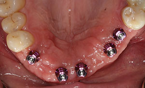
| Figure 1. Without anesthesia, the healing abutments were removed and replaced with transfer assemblies that duplicated the internal position of each implant. | Figure 2. Medium and heavy body VPS materials (Panasil [Kettenbach LP]) were used for a final, accurate impression. The impression copings were threaded into lab analogues and then placed into the impression. |
 |
 |
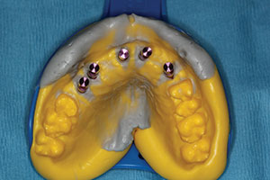
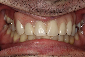
| Figure 3. The retracted aesthetics of the patient’s old conventional partial denture with clasps. | Figure 4. The dental laboratory team created a master cast with the gingival soft tissue mask (Gingifast [Zhermack]). This material mimics the soft-tissue contours well. A polyurethane material (Polyurock [Cendres + Metaux]) was used to fabricate the master cast. There is only a 0.007% shrinkage of this material, providing an accurate master cast. |
Clinical Treatment
Following integration of the dental implants (Hahn Tapered Implant System [Glidewell Laboratories]) placed approximately 4 months previously, the 5.0-mm healing abutments were unthreaded and replaced with transfer impression copings. Although these impression copings seemed to engage precisely into the implants, a radiograph was taken to ensure complete seating of the metal to metal components. A closed-tray technique was utilized since the implants were nearly parallel. If the implants had been angled from each other, an open-tray technique would have been indicated and used. Because the healing abutments extended into the oral cavity, there was no need for any local anesthesia. This becomes a real advantage in using healing abutments when proper initial torque of the implants is achieved, rather than burying the cover screws. Figure 1 illustrates the transfer impression coping in place. Note the ideal spacing of the implants (Hahn Tapered Implant System) that was achieved through CBCT diagnosis and planning with virtual placement of the implants using Invivo5 (Anatomage) computer software. The digital treatment plan was created for implant placement and crown shape and position. We were able to confirm screw access through the palatal aspect of the prosthesis. A surgical guide was fabricated using this information.
Medium and heavy body vinyl polysiloxane materials (VPS) (Panasil [Kettenbach LP]) were used for the final impression. The transfer assembly was unthreaded from the implants, and laboratory analogues (they mimic the internal design of the dental implants) were placed. Figure 2 shows how the entire system is inserted into the final impression. Figure 3 shows the retracted aesthetics of the patient’s old conventional partial denture. Note the clasps and extreme pink acrylic. In diagnosing, it is important to realize that there will be a need for gingival-shaded material in the final bridge to maximize the form of the teeth (Figure 3).
The Transitional Implant Bridge
From this accurate, final impression, the dental laboratory would create the master cast using a gingival soft-tissue mask material (Gingifast [Zhermack]). This material mimics the soft-tissue contours. Polyurock is the polyurethane material used to fabricate the master cast (Cendres + Metaux). There is only a 0.007% shrinkage of this material; thus, it provides an accurate master cast (Figure 4). A digital image design was created from a 3Shape Scanner (3Shape) and evaluated by the dental technician and the doctor to establish ideal contours, length, and position. The transitional PMMA (Zirlux Temp Multi [Henry Schein]) bridge was then milled (IMES-ICORE 5X Mill: Model 350I [Dental Axess]) (Figure 5) and mounted on a semi-adjustable articulator (Artex) to check the occlusion (Figure 6). Before delivering the transitional screw-retained implant bridge, the healing abutments were removed, revealing the healthy pink tissue cuffs that had been created (Figure 7).3 The appliance was passively seated and threaded into place using the abutment screws, which were torqued to 35 Ncm. The transitional implant bridge was seated (Figures 8 and 9), and the patient was instructed to evaluate the restoration based on the shape/shade of the teeth and his ability to maintain good oral hygiene at home. Any patient feedback/comments were then considered and incorporated into the design of the final prosthesis (Figure 9).
 |
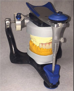 |
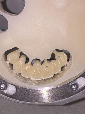
| Figure 5. The IMES-ICORE 5X: Model 350I (Dental Axess) milling machine was used to mill the transitional PMMA (Zirlux Temp Multi [Henry Schein]) bridge and the final zirconia bridge (Prettau Zirconia [Zirkonzahn]). | Figure 6. The transitional (PMMA) milled appliance was fabricated using the digital preoperative design and mounted on a semi-adjustable articulator (Artex) to check proper occlusion and excursive movements and contacts. |
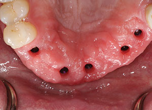 |
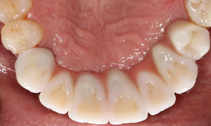
| Figure 7. Occlusal view of the healthy pink-tissue cuffs created by the healing abutments. |
 |
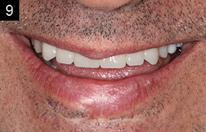 |
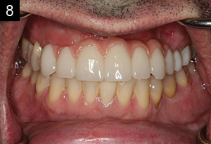
| Figures 8 and 9. The seated transitional bridge. A digital image design was created from a 3Shape Scanner (3Shape) and evaluated by the dental technician and the doctor to establish ideal contours, length, and position. The PMMA transitional screw-retained bridge was milled. Laboratory titanium non-engaging cylinders (Glidewell Laboratories) were used for the screw-retained prosthesis. The patient was allowed to evaluate the transitional prosthesis for a few weeks prior to final zirconia bridge fabrication. |
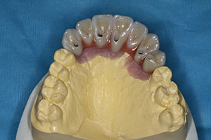
Once the function and aesthetics were approved by our patient, the dental laboratory team began the fabrication of the final zirconia bridge (Prettau Zirconia [Zirkonzahn]; IMES-ICORE 5X Mill: Model 350I) (Figure 10). Next, the zirconia bridge was cut back by the dental technician. Prettau Zirconia 98 X 25 liquid was painted onto the cut-backed zirconia and then placed into the oven to sinter. This maximized the underlying shading and allowed depth to be created in the final porcelain work. Figure 10 shows the occlusal view of the final implant-retained bridge with the screw access holes placed on the cingulums. Layering porcelain (IPS e.max Ceram [Ivoclar Vivadent]) was applied to the facial surfaces of all the zirconia units to create a depth of shade for an optimal aesthetic outcome.
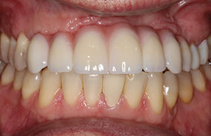
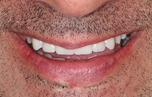
Figure 11 illustrates the side-by-side comparison of the final zirconia bridge (shown on the left) and the transitional bridge (shown on the right). Basic contours are maintained with improvement on the shade of the final restoration. Figures 12 and 13 show the zirconia bridge seated. Note that from the occlusal view, the 5 access holes are covered with composite resin. The abutment screws were torqued to 35 Ncm.2 The smile line of our patient can be seen in Figure 14. He was thrilled with the permanent function and the final aesthetics and anxious to continue treatment that would include aesthetic dentistry in his mandibular arch. The final CBCT view (Figure 15) of the implant shows complete engagement of the screw-retained abutments into the strategically placed dental implants.
 |
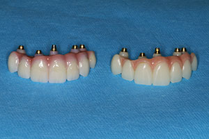 |
| Figure 10. Occlusal view of the final implant-retained bridge. Layering porcelain (IPS e.max Ceram [Ivoclar Vivadent]) was applied to the facial surfaces of all units. Prettau Zirconia 98 X 25 liquid was painted in multiple shades to optimize the aesthetics. | Figure 11. Side-by-side comparison of the final zirconia bridge (left) and the transitional bridge (right). |
 |
 |
| Figure 12. The final bridge was threaded to place and the occlusion was carefully evaluated. | Figure 13. Occlusal view of the bridge in place. Note that the 5 access screw holes were covered with a composite resin. |
 |
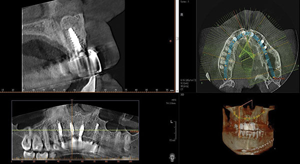 |
| Figure 14. The smile line of our patient, who was thrilled with the permanent function and final aesthetics. | Figure 15. The final CBCT view of the implant, showing the complete engagement of the screw-retained abutments. |
CLOSING COMMENTS
Over recent years, our patients have become more aware of the dental options available and more involved in determining the type of dental therapy that they receive. Therefore, it is critical that dental health professionals keep up to date with modern technologies and dental materials.
CBCT analysis helps in idealizing the treatment plans prior to any invasive procedures on the patient. The days of simply placing dental implants where there is adequate bone are gone. Today, our surgical considerations must be directed by prosthetically driven decisions. Software virtual design is an impressive means of creating the final aesthetics and maximizing implant placement. Once we realize that guided-surgical procedures help create idealized positioning, and that high-quality dental implants provide initial stability and minimize bone loss at the bone crest, we are way ahead. Choosing the right implant and the correct prosthetic components for each situation provides predictable integration. With the right tools and the support of a reliable dental laboratory team, astute clinicians can create optimal results, including those made under challenging circumstances.4
References
- Christensen GJ. BruxZir and e.maxCAD: Superior Clinical Performance at 3+ Years. Clinicians Report. June. 2104:7(6):1-3.
- Preciado A, Del Río J, Lynch CD, et al. Impact of various screwed implant prostheses on oral health-related quality of life as measured with the QoLIP-10 and OHIP-14 scales: a cross-sectional study. J Dent. 2013;41:1196-1207.
- Lang NP, Löe H. The relationship between the width of keratinized gingiva and gingival health. J Periodontol. 1972;43:623-627.
- Turkyilmaz I, Company AM, McGlumphy EA. Should edentulous patients be constrained to removable complete dentures? The use of dental implants to improve the quality of life for edentulous patients. Gerodontology. 2010;27:3-10.
Dr. Kosinski is an Affiliated Adjunct Clinical Professor at the University of Detroit Mercy School of Dentistry and is the associate editor of the AGD Journals. He is a past president of the Michigan Academy of General Dentistry. Dr. Kosinski received his DDS from the University of Detroit Mercy Dental School and his Mastership in Biochemistry from Wayne State University School of Medicine. He is a Diplomat of the American Board of Oral Implantology/Implant Dentistry, the International Congress of Oral Implantologists and the American Society of Osseointegration. He is a Fellow of the American Academy of Implant Dentistry and received his Mastership in the Academy of General Dentistry. He has received many honors, including Fellowship in the American and International Colleges of Dentists and the Academy of Dentistry International. He is a member of Omicron Kappa Upsilon and the Pierre Fauchard Academy. He was the University of Detroit Mercy School of Dentistry Alumni Association’s “Alumnus of the Year,” and in 2009 and 2014 he received the Academy of General Dentistry’s Lifelong Learning and Service Recognition. He has published more than 160 articles on the surgical and prosthetic phases of implant dentistry. He can be reached at (248) 646-8651, via email at drkosin@aol.com, or via the website smilecreator.net.
Disclosure: Dr. Kosinski reports no disclosures.
Mr. Menoutes, certified dental technician (CDT), is a graduate of Ferris State University (1993) with a degree in dental technology. He did an internship with the late David J. Guelde, CDT, MPT, from Clarkston, Mich. He has been doing CAD/CAM design and milling for the past 11 years and has 20-plus years of experience with dental implant prosthetics. He is president of the Michigan Association of Commercial Dental Laboratories. James is the owner of Michigan Implant, Inc, and the co-owner of Removable Concepts in Flint, Mich. He can be reached at (810) 733-0909 or via email at xcelds@aol.com.
Disclosure: Mr. Menoutes reports no disclosures.
Related Articles


