


INTRODUCTION
For anyone who has been involved with an All-on-4 procedure, the thought of going into surgery with no interim ready to convert may not only sound strange but quite scary. As prosthodontists, we have been involved in hundreds of these cases and had the teeth ready to convert hundreds of times. So why would we now intentionally begin a surgery without the teeth? Technology!
While we have had the technology and digital know-how for years to do this, we have resisted. We started immediately loading full arches when the only method available was converting a traditional denture. When stackable guides started becoming popular, we transitioned to this for the improved accuracy of implant placement and ease of conversions. With both of these methods, we had the problem of interims breaking weeks to months into the process. This would significantly impact the experience patients had and would put their implants at risk. So, when Smart Denture Conversion abutments came to market, we were early adopters. They ease conversions but also provide a prosthesis with more strength. This became our method of choice for conversions in our practice. We started using them with dentures and later began milling prosthetics supported by stackable guides. To this day, we still use stackable guides and Smart Denture Conversion abutments with great success and ease. So why try something new?
CASE REPORT
Allison presented to our dental implant center with a failing maxillary dentition. We discussed her options, and she elected to go with the All-on-4 option and replace all of her maxillary teeth with a prosthesis supported by at least 4 dental implants. Typically, this prosthesis ideally requires 15 mm of restorative space to make room for not only the teeth but the gingiva as well. Through our implant planning, it was found that if we wanted 15 mm of restorative space, we would not have enough bone for the implants. Allison had a short maxilla, so we changed the plan. We transitioned to a full-arch, implant-supported bridge—what Misch called an FP1 prosthesis. This prosthesis is just bridges replacing the teeth, with no gingiva. So, what was the challenge?
We have enjoyed years and years of not having patients return with their interim prosthetics broken while waiting for their implants to integrate. We feel much of our success was from drawing a line and not crossing it. Making an immediate load conversion of an FP1-type prosthesis comes with concern—we can’t make a thicker interim prosthesis since the prosthesis itself is replacing just the teeth. So what do we do?
We have had the software and 3D printers for years, capable of designing teeth and printing them all on the day of surgery. When doing this, we can design the interim to sit directly on the multi-unit abutments and be held in place with Rosen screws (Rosen Screws). This combination provides the added strength in a thinner prosthesis but isn’t possible without technology. I would like to walk you through the day of surgery.
Before Surgery
Regardless of the route we choose for getting our patients into their interim prostheses, it always begins with a records appointment. We discuss with patients their goals for their new smiles. Once we know where we are going, we evaluate where we are at now (midline, incisal edge position, vertical, occlusal plane, etc). We also take photos, intraoral scans (TRIOS [3Shape]) (Figure 1), and CBCT scans (OP 3D [DEXIS]).
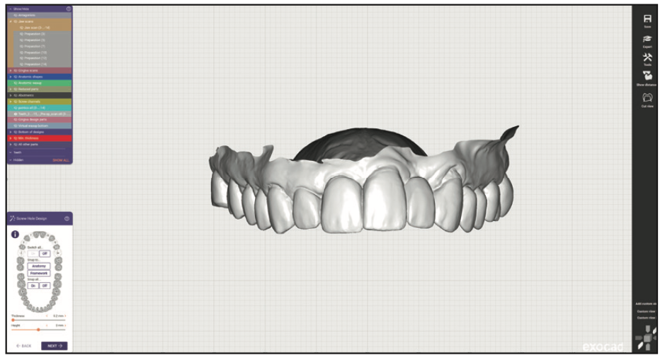
Figure 1. Preoperative intraoral scan.
From everything we gathered at Allison’s first visit, we designed her teeth digitally with exocad (exocad America) (Figure 2). We referenced the list of changes and photos to ensure the design achieved her goals. Something to note here is that while we had designed the new teeth, we still had the old teeth aligned to them (transparent in the image)—this is important later.
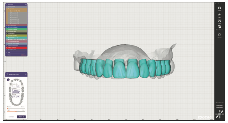
Figure 2. Teeth designed in exocad (exocad America).
After the teeth are decided, they are brought into the implant planning software (Blue Sky Plan [BlueSkyBio]). When placing implants for an FP1 prosthesis, it is critical to position them directly beneath the teeth they are replacing. The last thing you want is an implant going into an embrasure space where a papilla is supposed to be. While it is possible to place a full-arch prosthesis directly to implants, it is very difficult. It is the reason multi-unit abutments were created. So, for Allison’s plan, the implants and abutments were planned below the planned teeth at Nos. 3, 5, 7, 10, 12, and 14 (Figure 3). After the implants and abutments were confirmed, this was exported out, finalized as a final prosthesis design (Figure 4), and later used in the guide fabrication (Figure 5).
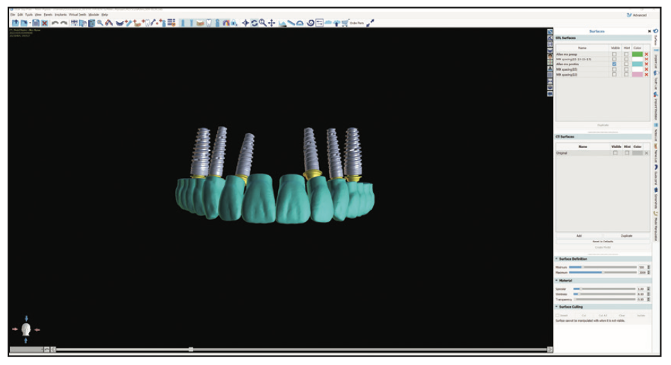
Figure 3. Implants placed in Blue Sky Plan (BlueSkyBio) directly below the teeth.
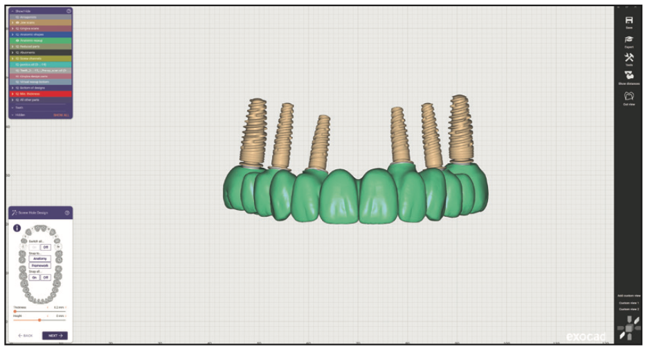
Figure 4. The prosthestic design adapted to the planned implants.
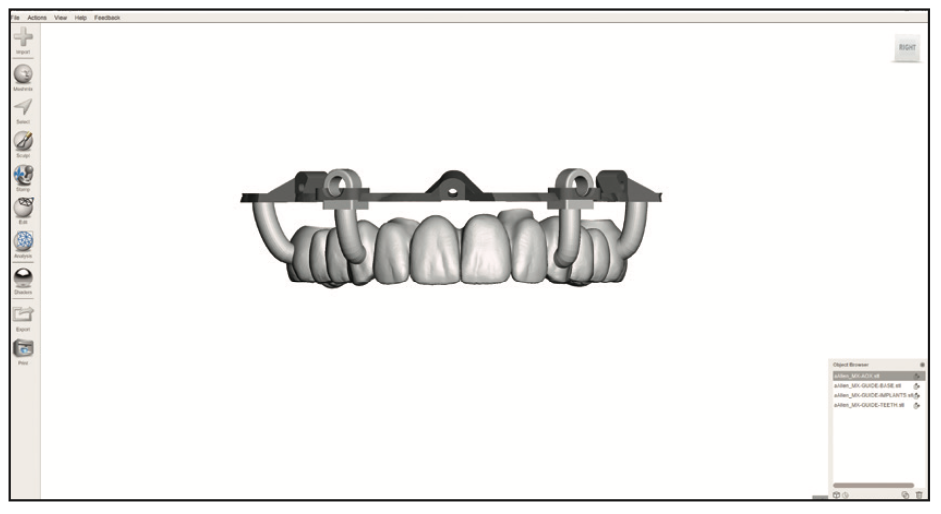
Figure 5. The planned prosthetic was incorporated into the surgical guides.
All of the planning we completed was brought into 3D editing software (Meshmixer [Autodesk]) and used to fabricate the surgical guides used at the surgery. Allison’s guides started with a tooth-supported guide attached to a foundation guide. This foundation guide stayed attached to her maxilla for the duration of surgery, serving as a stable base for a variety of other guides.
To summarize the presurgical planning goals, we then had a variety of surgical guides designed and fabricated, as well as the interim prosthesis designed but not fabricated (milled or printed).
Surgery
After Allison was sedated, our surgery started. After administering local anesthetic to her maxilla, a facial flap was laid from left to right. When using a foundation guide with stackable pieces, this flap needs to be extended further apically than usual. The foundation guide starts attached with plastic pins to a tooth-supported guide. This allows us to use a stable starting point as a reference to ensure we’ve accurately transferred the digital plan to surgery. With the one guide securely fitted to the teeth, we secured the foundation guide to her bone.
Note that with this technique, we made Allison’s foundation guide in titanium (Titanium 98 mm Disc [Imagine USA]). As you will see, we needed the guide to stay exactly where we put it for the duration of the procedure. Our lab (Renew Full Arch Lab) designed a millable foundation guide just for this technique. We wanted something more stable than 3D printed resin guides. We sandblasted the titanium so that it scanned easier. Also note that, with her case, we opted to use screws (Pro-Fix [Osteogenics]) rather than pins to secure the guide. Again, this was for improved stability. The third design element to ensure stability was to have the guide touch the bone in those few places where the screws go in. We have pinned a lot of floating resin guides for All-on-4 surgeries and can assure you that these 3 changes make a significant difference in stability.
When the screws were in, the plastic pins were removed, and the tooth guide was taken out (Figure 6). The next step was important to this particular technique—making a scan of the patient’s teeth and the foundation guide (Figure 7). This was the first of 2 scans used to design her interim prosthesis.
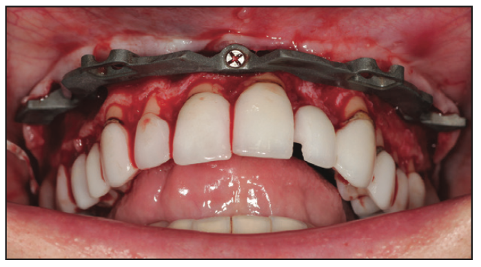
Figure 6. After the foundation guide was screwed to the bone, the tooth guide was removed.
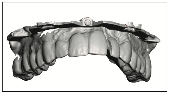
Figure 7. The teeth and foundation guide were scanned with TRIOS (3Shape).
Then it was time to extract the teeth. With an FP1 procedure, you aren’t removing the bone to make room for an All-on-4 prosthesis. Instead, you are trying to maintain as much bone as possible since only bone can support the gingiva you hope will form the papillae (Figure 8). But we needed to remove any bone that would prevent the future teeth from seating. To guide this very specific alveoplasty, we took the same design of the arch and added it to the stackable guide. This gave us a clear view of the bone that needed to be removed (Figure 9). The goal was to remove enough bone to make room for gingiva (1.5 to 2.0 mm).
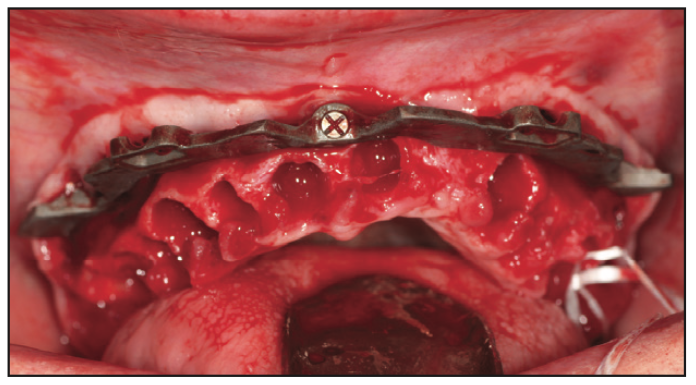
Figure 8. Teeth were extracted with an effort to preserve as much bone as possible.
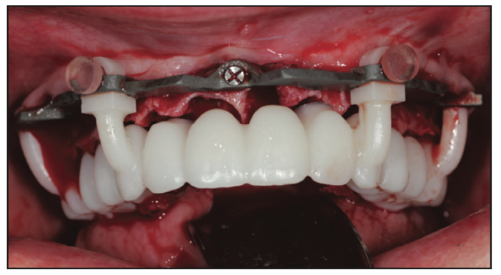
Figure 9. The designed prosthesis was printed and rested on the foundation guide.
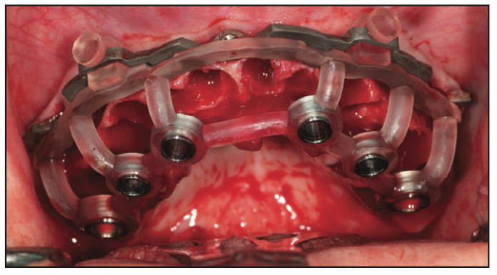
Figure 10. The implant guide was used to accurately place the implants.
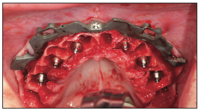
Figure 11. Multiple abutments were placed on the implants.
Adequate bone was removed, and the implant guide was used to place the dental implants (GM Drive [Neodent]) according to our plan (Figure 10). Then the multi-unit abutments were placed (Figure 11), ensuring no contact with bone (note that it will likely require further alveoplasty). The abutments were then torqued to place. The next step is the second most important part of this technique. Photogrammetry requires that we scan something that acts as a fiduciary to relate its highly accurate data to the intraoral scan. With our scanner, there are cylinders for this purpose. These were placed on Allison’s multi-unit abutments and scanned (Figure 12). This scan included the foundation guide and cylinders (Figure 13). These 2 scans (teeth with guide and guide with cylinders) were immediately given to the lab for alignment.

Figure 12. The iMetric cylinders were placed on the multi-unit abutments.
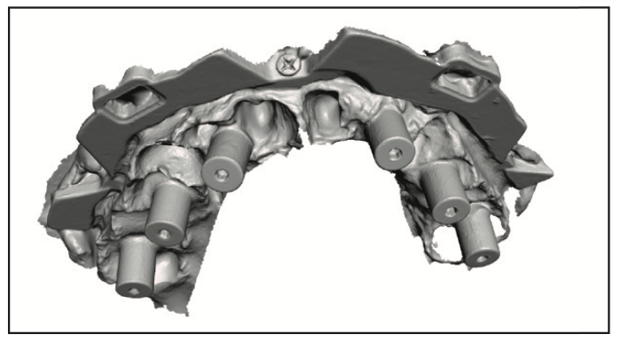
Figure 13. The foundation guide and iMetric cylinders were scanned with the TRIOS.
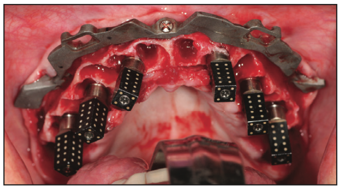
Figure 14. The iMetric scan bodies were placed on the multi-unit abutments.
The cylinders were removed and replaced with the photogrammetry scan bodies (Figure 14). These were used with the photogrammetry unit (iCam [iMetric 4D]) to scan the implant positions. It scans all of the scan bodies in less than a minute and provides better accuracy than most desktop scanners and traditional jigs. This data was also given to the lab. It is this technology that makes this technique possible.
Photogrammetry has been around for decades in a variety of industries but is relatively new to dentistry. Intraoral scanners are very accurate when scanning small objects like teeth. But they fail when asked to scan longer distances, such as, for example, one side of an arch to the other. Desktop scanners have traditionally been used to scan for full-arch, implant-supported prosthetics, but they require a model. Getting a verified abutment-level model is best achieved through taking preliminary impressions and then final impressions with the use of a jig. Photogrammetry gets better accuracy within minutes. It’s a beautiful thing and a must for clinicians doing a lot of full-arch implant dentistry.
When the scan is complete and sent to the lab, they can finalize the design. In the meantime, one must graft around implants, graft all sockets, and suture. After the teeth are ready, they are inserted, and Rosen screws are used to secure them. Rosen screws are designed to provide a wedging effect and are meant to be hand-tightened. Once the teeth were inserted, occlusion was dialed in, and then screw access holes were filled with PVS.
Lab Work
The key to designing quickly at the time of surgery is that the design is done before surgery but is just missing the implant connections. With 2 intraoral scans and a photogrammetry scan, the rest is easy. All 3 scans are aligned, and the design is adapted to the implant positions. I’ll walk you through the details.
When the 2 intraoral scans were sent to the lab during surgery, the lab started the sequence of alignments. Remember, the design of the interim was already aligned with the preoperative scans of her failing dentition. The first scan from surgery has 2 important things: the current teeth and the foundation guide. The teeth in the first new scan are used to align this scan to the pre-op scan (Figures 15 and 16). This relates the foundation guide to the interim design. The second new scan has 2 important things as well: the foundation guide and the cylinders. This scan is aligned with the first new scan using the foundation guide as the common reference between them (Figures 17 and 18). These 2 alignments achieve a very important goal: to align the interim design to those photogrammetry cylinders (Figure 19). We can then use those cylinders to align the highly accurate photogrammetry data to the scene (Figure 20), which means the implant positions are now where we need them. The final step is adapting the interim design to the implant positions (Figure 21).
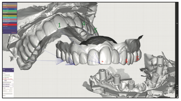
Figure 15. Common points were selected between the first surgery scan and the preoperative scan.
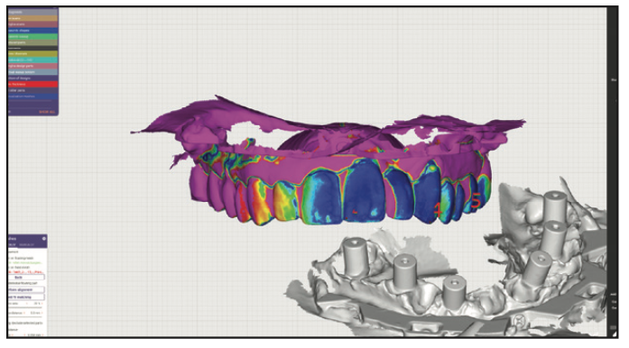
Figure 16. The exocad software used its alignment algorithm to match the scans (dark blue is considered a perfect alignment).
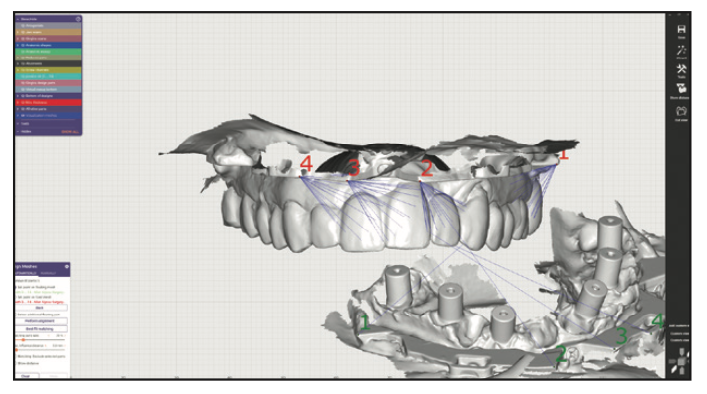
Figure 17. It’s the same idea in the sec- ond scan: The common points on the 2 guide scans are selected.
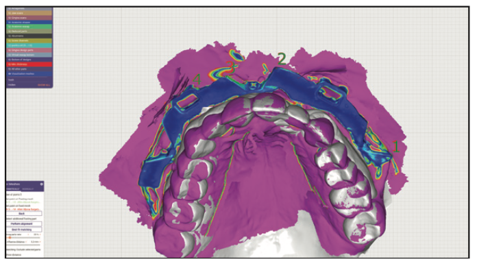
Figure 18. The dark blue denotes great alignment between the guide in scan 1 and scan 2.
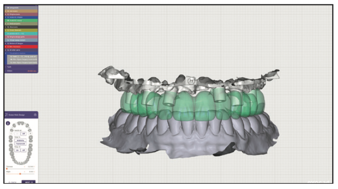
Figure 19. The iMetric cylinders were aligned to the presurgery interim design.
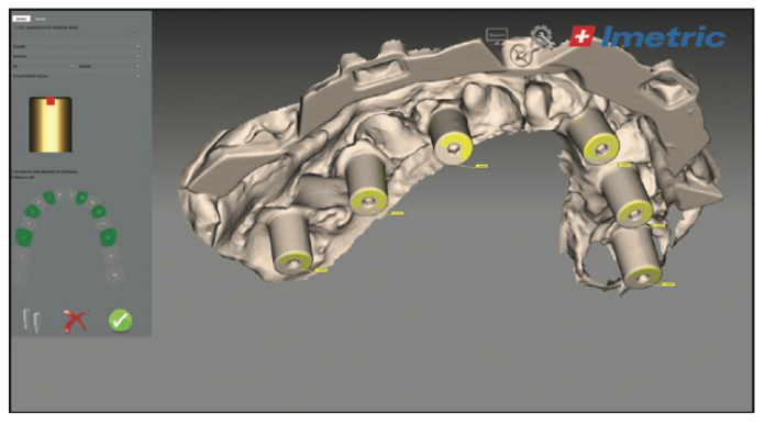
Figure 20. The scan of the cylinders was used to align the photogrammetry data.
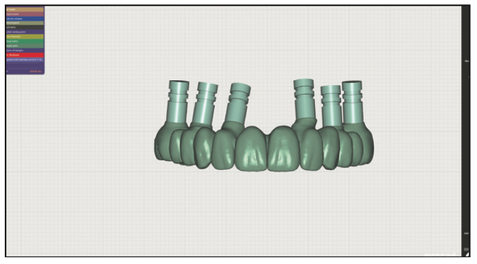
Figure 21. The presurgery design was adapted to the newly scanned implant positions.
The next step in the lab is to 3D print the interim design. It is important to note certain requirements of a printer used for this purpose. Not all 3D printers have adequate accuracy to print a design meant to fit a multi-unit abutment and screw. Second, it’s also important to consider the speed of the printer since the patient is waiting. And lastly, the printer has to be able to print a tooth-colored material (Rodin Sculpture [Pac-Dent]) that can withstand occlusal forces.
The final lab step was to wash the print, cure it, and finish it. Allison’s interim prosthesis was washed twice in isopropyl alcohol and cured in a flash unit surrounded by nitrogen (Otoflash G171 [anax USA]). We then used pumice and acetyl polish to give the print a nice shine. It was then ready for insertion.
CONCLUSION
As you can see, this technique is a careful dance between the clinician and the lab. Each has very specific roles and must do them to the best of their ability to ensure success. We have the luxury in our practice to share a roof with the lab so that we can keep everything in-house. For our lab’s clients, we design the interim prostheses before surgery; they capture the scans; we align and adapt; and they print, finish, and deliver. This technique avoids traditional conversions and delivers more predictable, custom interims. This means we are more likely to hit our target goals and give our patients the smiles they are hoping for.
ABOUT THE AUTHOR
Dr. Farley is a surgical prosthodontist practicing in Mesa, Ariz. He and his business partner own and operate Revive Dental Implant Center and Renew Full Arch Lab (renewdigitaldesign.com), where they utilize the newest technologies to provide high-quality full-arch prosthetics. Dr. Farley also teaches live and online courses through their education center, DigitalDDS (digitaldds.com). He can be reached at nfarley@revivedental.com.
Disclosure: Dr. Farley reports no disclosures.


