Dr. Paul Feuerstein, Editor-in-Chief of Dentistry Today, invited Tom Lee to give a detailed overview of the precepts of occlusion as they have been taught for many years, including by his father, Dr. Robert Lee, in the 1960s. The information here is complex and certainly gives us a reason to study the dynamics of bite relationships. Although the digital world is making inroads with virtual methods, these tried and true concepts still must be understood. Many of our readers have done extensive studies at various institutions of higher education, and there are indeed different philosophies. Tom is giving us a starting point here for further discussion.
INTRODUCTION
This article will focus on the ABCs (axis, bite, and chewing) of occlusion and articulation that can be easily implemented to create restorations that require fewer adjustments, saving time and reducing stress. The initial step in reducing positive errors in articulation begins with accurate impressions and bite records, as any error in the technique or material will create a high restoration. All philosophies have the same objective of equal contacts of the occluded teeth with no interferences in all movements. Laboratory technicians can achieve this objective on whatever articulator they may use. Yet most restorations still need adjustments when placed in the patient’s mouth because of inaccurate impressions and/or positive errors in the axis, bite, and chewing of occlusion and articulation.
An articulator is an instrument that represents the temporomandibular joints (axis) or jaws to which study casts may be attached to simulate the static (bite) and dynamic (chewing) relationships between the occlusal surfaces of the teeth during mandibular movements. Positive errors occur when the articulator undercompensates for mandibular movements, resulting in a positive feature on the occlusal surface where that feature should be smaller or nonexistent.1 Negative errors occur when the articulator overcompensates for mandibular movements, resulting in a negative feature on the occlusal surface, which allows the teeth to disclude more freely.1 Positive errors can create interferences that may need to be adjusted in the axis (opening and closing movements), the bite, and chewing (envelope of function movements) depending on the discluding factor of the protrusive pathway, influence of the Bennett movement, and steepness of the anterior guidance.
AXIS
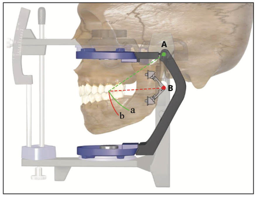
It is important to relate the teeth to the patient’s axis to be able to simulate more accurate opening and closing movements in an articulator. The most common error in relating study models is using a simple hinge articulator without the use of a face-bow. The axis in simple hinge articulators (Figure 1, red point B) is always located below the patient’s axis (Figure 1, green point A). Therefore, simple hinge articulators produce more vertical opening and closing axis movements (Figure 1, red pathway b) than the patient’s opening and closing axis movements (Figure 1, green pathway a). This positive error in articulator axis movements can create interferences in the mesial inclines of the upper teeth and/or distal inclines of the lower teeth that will require adjustments.2 It is much better to have the articulator axis closer or a little above the patient’s axis to reduce positive errors for fewer adjustments of opening and closing movements of the axis.
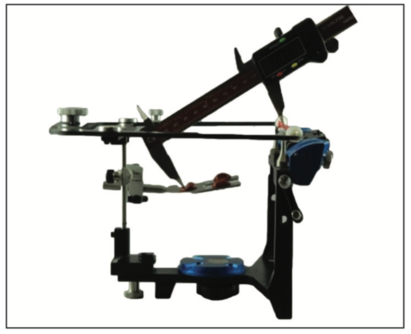
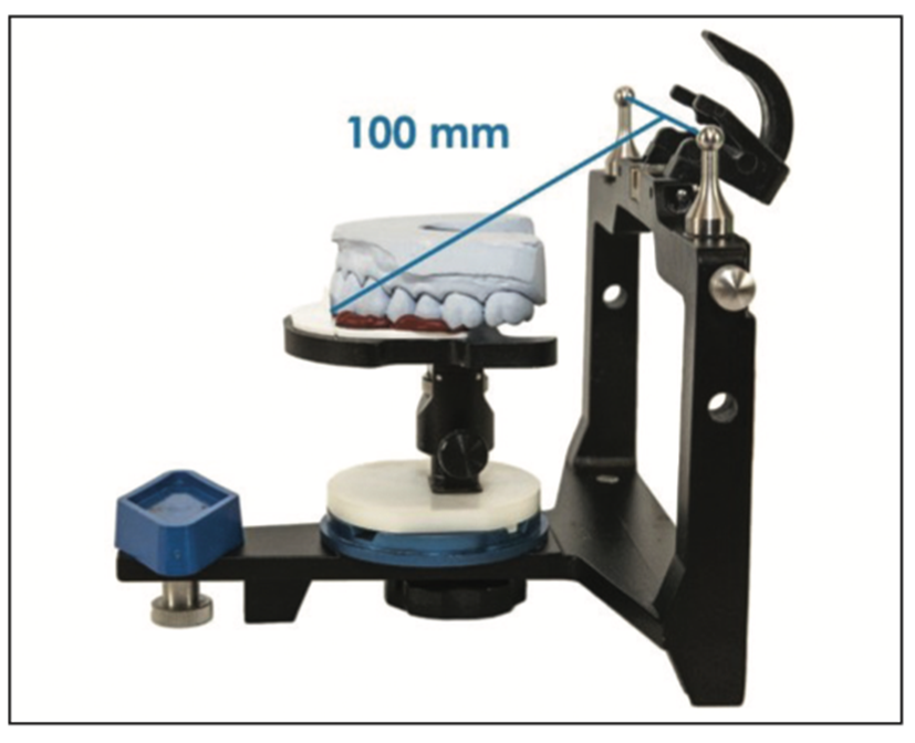
Research shows that a face-bow has a statistical average to the axis by referencing the patient’s ears, which relates the study models much closer to the patient’s axis to reduce positive errors.3 The Kois Dento-Facial Analyzer (DFA) is a simple instrument that incorporates a 3D guide plane to reference how the occlusal plane relates to the face for aesthetics, as well as having a functional relationship of the teeth to the axis based on an average axis-incisal distance of 100 mm (Figure 2).4 This 100-mm-average axis-incisal distance is supported by Monson’s Spherical Theory (4 in = 101.6 mm)5 and Bonwill’s Equilateral Triangle,6 as well as other research showing the Kois DFA to be as functionally accurate as a face-bow.7,8 The average 100-mm axis-incisal distance is engineered into the Kois Platform on the articulator, which can mount study models with or without the use of the Kois DFA (Figure 3).4 This standard functional mounting without a face-bow seems to place the articulator axis above the patient’s axis to create a negative error in opening and closing movements of the axis.
The steps are as follows:
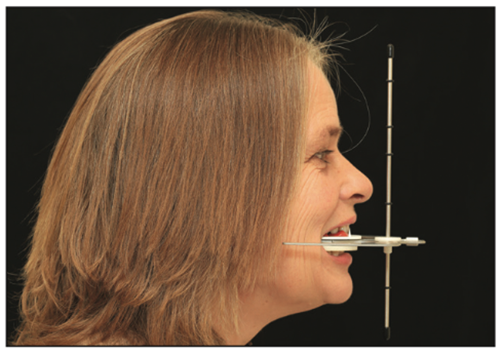
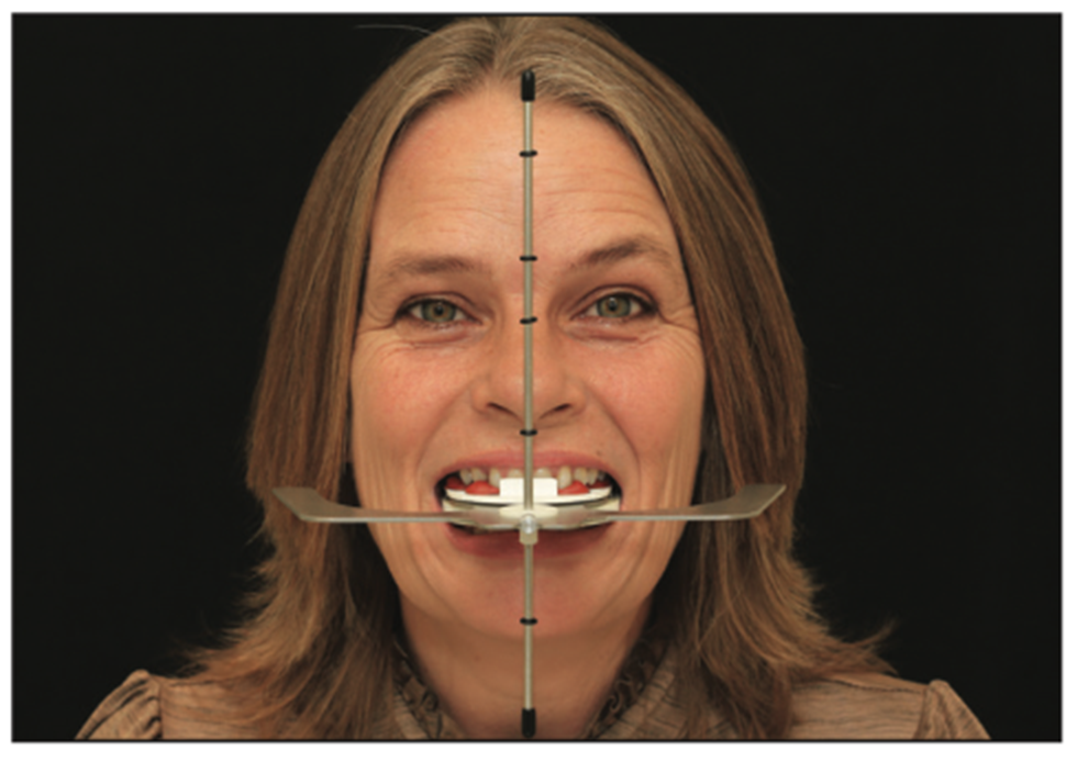
Step 1. Assemble the Kois DFA and add bite registration material to the Kois Index Tray. Insert the Kois DFA into the patient’s mouth and place the vertical wall on the Kois Index Tray to the facial of the central incisors (Figure 4). This will register and transfer the central incisal edge of the 100-mm axis-incisal distance for function.
Step 2. Align the vertical rod to the patient’s facial midline and level the lateral wings (Figure 5). Keeping the vertical rod and lateral wings aligned, push up lightly until a tooth touches the tray and then hold until the material sets. This will register and transfer any cant of the occlusal plane related to the horizon and facial midline for aesthetics.
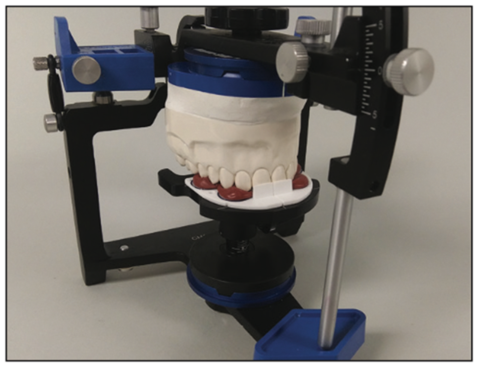
Step 3. Index the Kois Index Tray to the Kois Adjustable Platform on the articulator and orient the upper study model into the impression on a horizontal Kois Index Tray. The incisal edge is now 100 mm from the axis of the articulator for function (Figure 6). Mount the study models to the articulator in the usual manner.
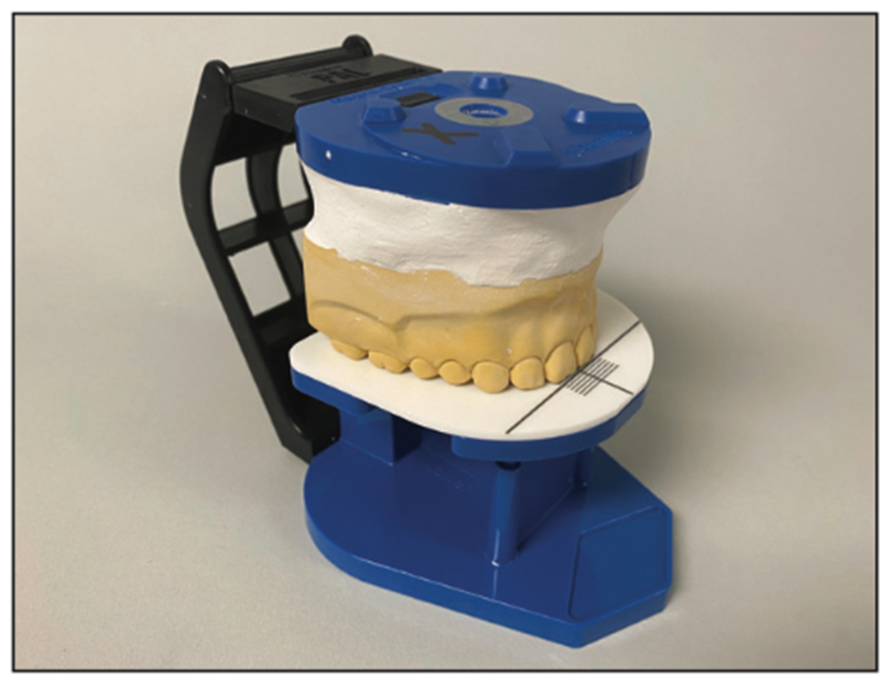
Optional. For a standard functional mounting without a face-bow, simply place the upper study model on the Kois Platform with the incisal edge to the 100-mm line on the waxing guide (Figure 7) (PAL 2.0 shown).
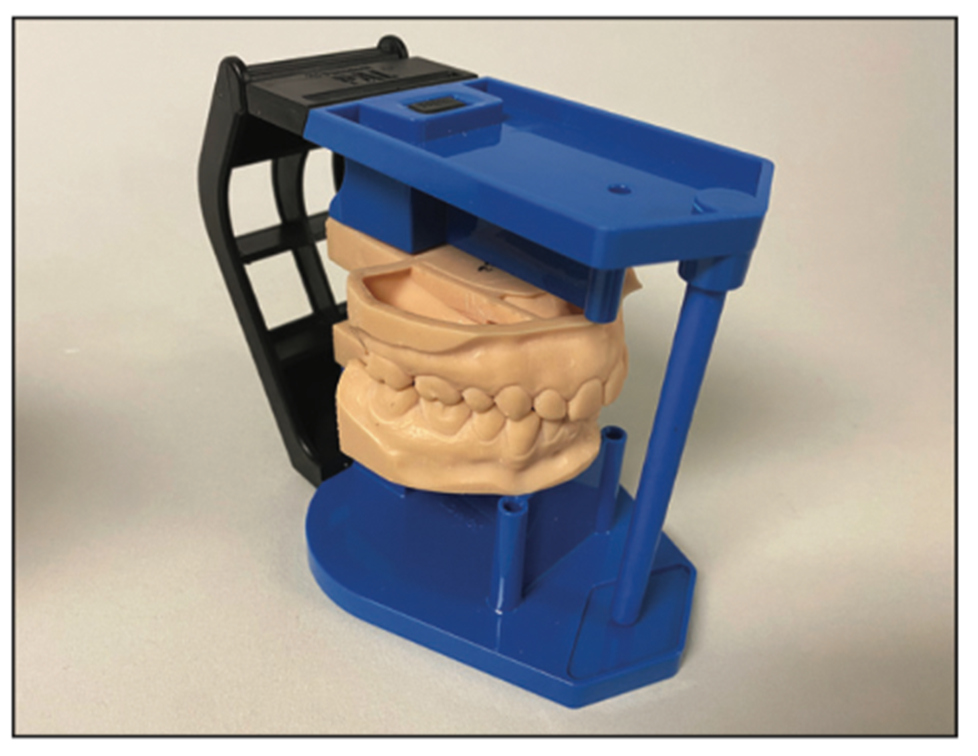
The Panadent PAL 2.0 Articulator System with an integrated Kois Platform has the same anatomical axis as the full-size articulator and is designed for general and digital dentistry (Figure 8).
BITE
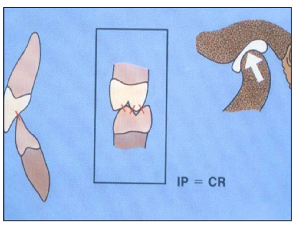
All dentists use marking ribbons to mark and adjust any high spots to achieve equal contacts of the teeth when the patient bites (maximum intercuspation). It makes anatomical sense to have the jaw in a physiologic position with the condyles against the disc orthopedically aligned and centered in the fossa when all teeth are occluded with normal neuromuscular function (Figure 9).
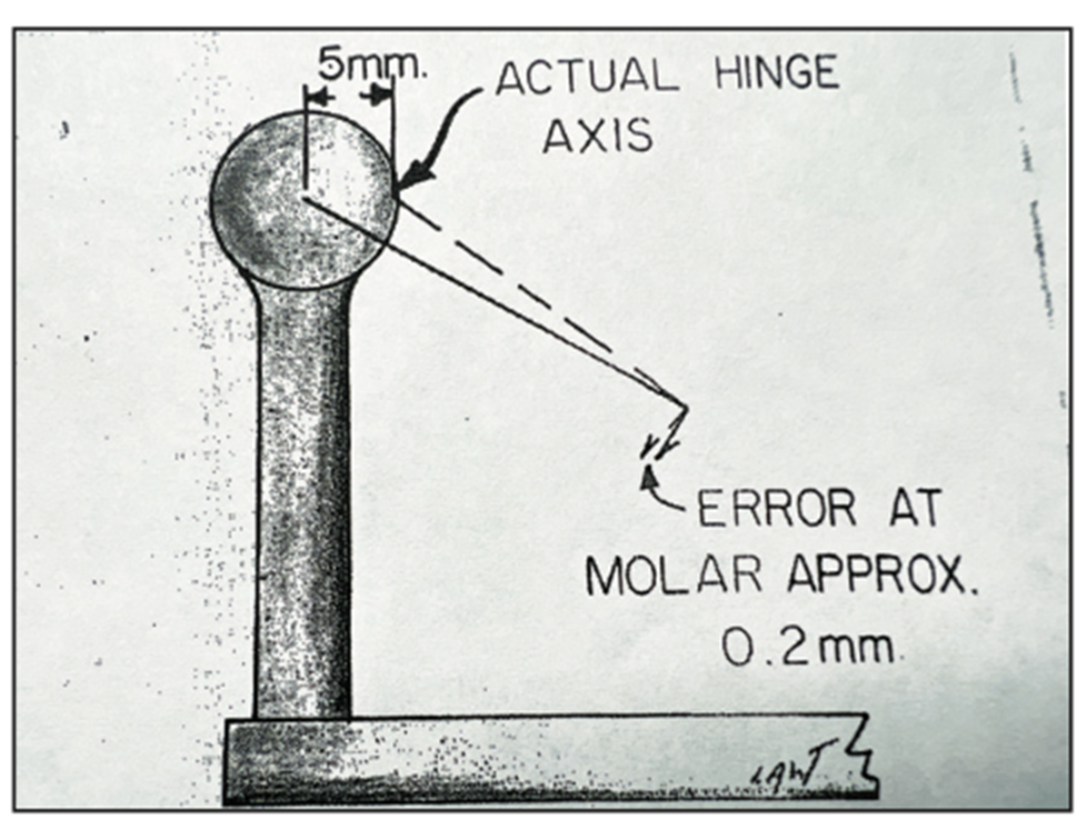
Since the articulator axis is not the true hinge axis of the patient when using a face-bow or Kois DFA, changing vertical dimension of occlusion (VDO) on the articulator can create positive errors or discrepancies in the bite (Figure 10).3 If changing VDO, it is recommended to take an interocclusal record at the VDO from which the restorations, prostheses, or occlusal splint will be fabricated. This will reduce positive errors for fewer adjustments of the bite.
CHEWING
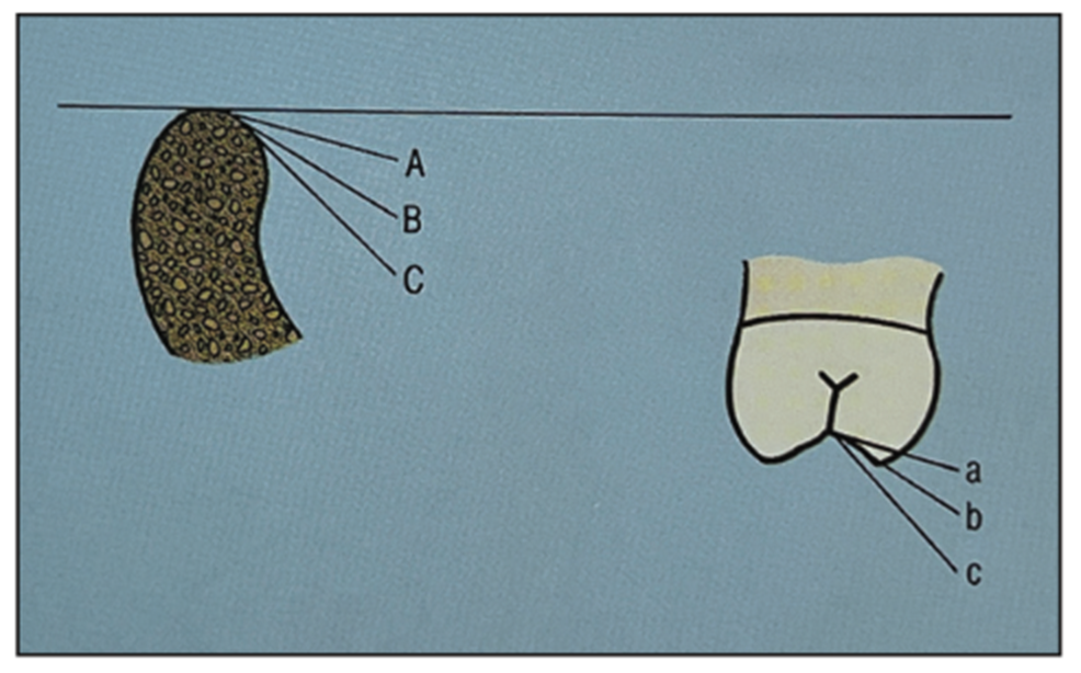
It is important to understand incising and lateral chewing movements (envelope of function) to simulate more accurate chewing movements in an articulator. The protrusive pathway (downward and forward movement of the condyles), together with incisal guidance, can have a discluding influence on the distal inclines of the upper teeth and/or mesial inclines of the lower teeth in incising chewing movements (Figure 11). Research shows that the angle of the protrusive pathway ranges from 20° to 75° to an axis-horizontal plane of reference. The protrusive pathway is the only discluding factor that can be programmed into an articulator that can be communicated with a protrusive interocclusal record to set the articulator. If no protrusive record is taken, it is recommended to set the articulator to a 20° protrusive pathway to reduce positive errors in incising movements of chewing.
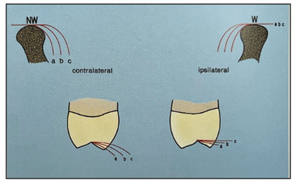
The Bennett movement (inward movement of the condyles), together with canine guidance, can have a discluding influence on the buccal and lingual cusps of the posterior teeth in lateral chewing movements (Figure 12). Research shows that Bennett movement ranges from 0.5 to 2.5 mm with approximately 90% of the population having 1.5 mm of Bennett movement or less.9 It is recommended to set the articulator to at least 1.5 mm of Bennett movement to reduce positive errors for fewer adjustments in lateral movements of chewing.
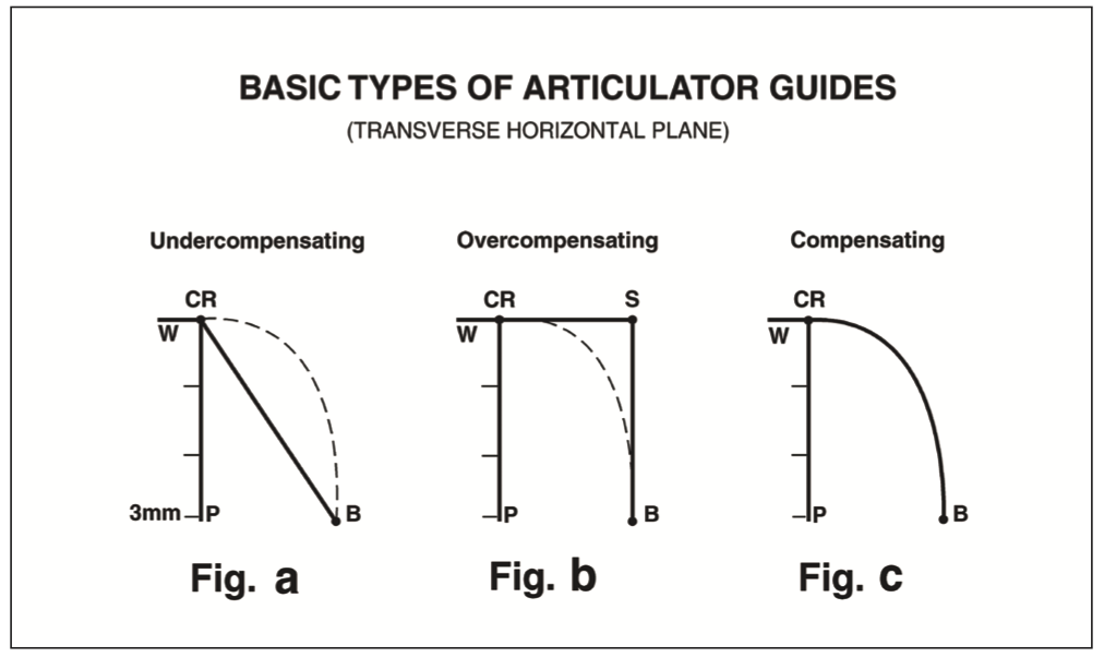
Most semi-adjustable articulators incorporate a straight-line, undercompensated Bennett guide (Figure 13, graph a), meaning the patient can move (curved dotted line) beyond the articulator guide (solid line), which may create positive errors in lateral chewing movements. The “Immediate Side Shift” articulator incorporates an overcompensated Bennett guide (Figure 13, graph b), meaning the articulator can move (solid “S” lines) beyond the patient’s movements (curved dotted line), which may create negative errors, but may also produce flatter anatomy. The Panadent articulator incorporates a curved-path, compensated Bennett guide (Figure 13, graph c), meaning the articulator moves more like the patient’s jaw movements, which may reduce positive errors for fewer adjustments in lateral movements of chewing.10,11
IN SUMMARY
Using the Kois DFA or doing a standard functional mounting to relate the teeth to an average anatomical axis may reduce positive errors for fewer adjustments in opening and closing movements of the axis.
Taking an interocclusal record at the VDO desired may reduce positive errors for fewer adjustments of the bite.
Setting the articulator with a 1.5-mm Bennett movement and a 20° protrusive pathway may reduce positive errors for fewer adjustments of incising and lateral movements of chewing.
REFERENCES
1. The glossary of prosthodontic terms: ninth edition. J Prosthet Dent. 2017;117(5S):e1-e105. doi:10.1016/j.prosdent.2016.12.001
2. Weinberg L.A. An Evaluation of Basic Articulators and their Concepts Part II. Arbitrary, Positional, Semiadjustable Articulators. In: J Prosthet Dent. 1963;13(4):645-663. doi:10.1016/0022-3913(63)90134-3
3. Teteruck WR, Lundeen HC. The accuracy of an ear face-bow. J Prosthet Dent. 1966;16(6):1039–46. doi:10.1016/0022-3913(66)90169-7
4. Kois JC, Kois DE, Chaiyabutr Y. Occlusal errors generated at the maxillary incisal edge position related to discrepancies in the arbitrary horizontal axis location and to the thickness of the interocclusal record. J Prosthet Dent. 2013;110(5):414–9. doi:10.1016/j.prosdent.2013.06.005
5. Monson GS. Applied mechanics to the theory of mandibular movements. Dental Cosmos. 1932;74:1039–53.
6. Bonwill WG. The scientific articulation of the human teeth as founded on geometrical, mathematical, and mechanical laws. D Item Interest. 1899;21:617–36; 873–80.
7. Lux LH, Thompson GA, Waliszewski KJ, et al. Comparison of the Kois Dento-Facial Analyzer System with an earbow for mounting a maxillary cast. J Prosthet Dent. 2015;114(3):432–9. doi:10.1016/j.prosdent.2015.02.022
8. Thompson GA, Nick C, Francisco P, et al. Comparison of two arbitrary cast transfer systems with a kinematic facebow for mounting a maxillary cast on a semiadjustable articulator. J Prosthet Dent. 2021;S0022-3913(21)00002-0. doi:10.1016/j.prosdent.2020.12.023
9. Lundeen HC, Gibbs CH. Chapter 1: Jaw movements and forces during chewing and swallowing and their clinical significance, In: Advances in Occlusion. John Wright Publishing; 1982:2-32.
10. Lee RL. Jaw movements engraved in solid plastic for articular controls. I. Recording apparatus. J Prosthet Dent. 1969;22(2):209–24. doi:10.1016/0022-3913(69)90248-0
11. Lee RL. Jaw movements engraved in solid plastic for articulator controls. II. Transfer apparatus. J Prosthet Dent. 1969;22(5):513-27. doi:10.1016/0022-3913(69)90227-3
ABOUT THE AUTHOR
Mr. Lee is president and owner of Panadent Corp. He is the son of Dr. Robert Lee, who published his research in the Journal of Prosthetic Dentistry in 1969, which led to the development of the Panadent Articulator System. He holds several patents for face-bow and articulator designs. Mr. Lee has published several articles and has lectured nationally and internationally with his extensive knowledge in articulator design and its relationship to occlusion and aesthetics. He can be reached at [email protected]
Disclosure: Mr. Lee is president and owner of Panadent Corp.