

The pursuit of excellence in endodontics was compromised until recently by the incompatibility of biologic demand with the technical limitations of the armamentarium available. The introduction of increasingly innovative nickel-titanium rotary instrumentation systems designed with crown-down vectoring has enhanced the architectural rendering of the anatomy and geometrical vagaries of the root canal space.1-3 Each portal of exit on the root face has biological significance. This includes bifurcations, trifurcations, the base of infrabony pockets, and apical termini. Increased irrigant volume can now access the full complexity of the root canal system, resulting in an optimized cleaning phase, thereby enhancing the degrees of success achievable.
Revision of the shaping and cleaning paradigm has followed a long and tortuous evolutionary process. A chronology of recent technical protocols demonstrates the extended timeline: Serial Instrumentation—Schilder 19744; Step Back—Mullaney 19795; Crown Down—Marshall 19806; Step Down—Goerig 19827; Balanced Force—Roane, 1985.8,9 There is an imperative that has driven this evolution; the elastic memory of all metal instruments drives them to a single wall as they navigate curvature. In the pre-NiTi era, the self-centering characteristic of the instrument was not a component of a computer-modeled design. As a result, canal shapes were “larger” to compensate for the presence of the curve.10
The root forms in a crown-down manner and the root canal system calcifies coronal-apically. Consistent with the morphogenesis of the root canal system, the new-millennium endodontic canal preparation has shifted emphasis in achieving apical shape through a crown-down approach. In order to effect a thorough shaping and cleaning of the entire root canal system and seal it permanently with a biologically inert obturating material, the operator’s focus has shifted toward first preparing the coronal aspects of canals in order to most effectively approach complex apical anatomies. By enlarging the most accessible coronal portion of the canal system first while conserving the original canal pathway, access to the apical portion is facilitated. Less resistance is encountered, and endodontic files undergo less stress.6,7,11-13
It is important to this discussion to note that the original descriptions of crown down merely meant progression from larger diameters and tapers to smaller diameters and tapers. This approach can be significantly different from a systematic approach that minimizes file engagement and stress while focusing on enlarging and cleaning of the canal in portions, from coronal to apical.
The elimination of constrictions in the coronal region of the canal with the crown-down approach reduces the effect of canal curvatures and provides better tactile awareness during apical cleaning and shaping.6,7,11,12 It enables irrigation to be effective to the depth that instruments reach. Furthermore, the majority of pulp tissue and microflora are removed before the apical third is negotiated, thereby minimizing the risk of toxic extrusion into the periapical regions.14,15 In addition, the working length is less likely to change during apical instrumentation because canal curvature has been reduced before working length is established.
It should be evident in the NiTi era that we are just now beginning to truly respect the pulp canal space as the defining parameter of shaping and cleaning; we are “listening to its voice” for the first time.16,17 For much of the hand instrumentation era, the defining shape for obturation procedures was the creation of a collar-like apical resistance and retention morphology.10 In the absence of variable taper instruments, with the preponderance of gates-glidden usage for coronal opening, and in an era still dominated by lateral condensation, over-extension was a potential result.
The creation of endodontic excellence, especially in the era of nickel-titanium techniques, demands strict adherence to preparation length, a thorough understanding of cutting dynamics, and awareness of the shape/design being created. The variable tapers in the instrument systems coming to market impart greater resistance to displacement in the apical third—the “Apical Control Zone” (ACZ)—and facilitate apical patency with minimal risk for the extrusion of thermolabile obturation materials.
THE APICAL CONTROL ZONE
The Apical Control Zone is a mechanical alteration of the apical terminus of the root canal space that affects the rheology of thermolabile gutta-percha, offering resistance and matrix-style retention form against the condensation pressures of obturation.18-20 This terminus region can be anatomically challenged, altered by pathologic resorption or iatrogenic misadventure. The zone demonstrates an exaggerated taper from the clinician-defined apical constriction, whether this is spatially a linear or point determination. This enhanced taper in the apical control zone provides resistance form against the condensation pressures of obturation and acts to prevent the extrusion of the filling material during obturation.
 |
| Figure 1. The components of the Apical Control Zone (ACZ) are graphically depicted. |
It is essential that small file sizes be used to “survey” the glide path to the apical foramen (Figure 1). Vagaries that include merging canals, curvature, dilacerations, division, et al must be “blueprinted” prior to the introduction of NiTi rotary systems. Properly done, an Apical Control Zone predictably ensures a round, symmetrical, well-cleaned apical foramen for obturation.
 |
| Figure 2. Roane defined his small, medium, and large Apical Capture Zones (referred to by the authors as Apical Control Zones) as Nos. 45, 60, and 80 preparations. The parameters he established were the following: small ACZ, No. 15 file to the radiographic terminus (RT), No. 45 file 1.5 mm back from the terminus; medium ACZ, No. 20 file to the RT, No. 60 file 1.5 mm back; large ACZ, No. 25 file to the RT, No. 80 file 1.5 mm back. |
As originally described by Roane,18 there should be predesigned preparations for each of 3 canal types. The control zone taper rate should vary from 1 to 2 mm per mm of canal length. Roane determined that this taper would provide a resistance of at least 4 times that of the canal shape itself, thus enabling the use of apical patency with minimal risk for the extrusion of the obturating materials. In his technique, 0.5-mm step backs created an operator-fabricated terminating taper prior to the continuum with the periodontal ligament, thereby eliminating the procedural nuances of the search for the CDJ (Figure 2).
THE NITI FILE SYSTEMS
The goal of this article is to structure a standardized comparison between the Apical Control Zones created by certain popular rotary NiTi instrumentation systems in the endodontic armamentarium: K3, Lightspeed, RaCe, ProTaper, and ProSystem GT.
 |
| Figure 3. For the purposes of standardization, each Apical Control Zone image was drawn to represent the apical one third of an “average-sized” mandibular molar, 22 mm in length. Anatomical crown height being approximately 10 mm, the root length of 12 mm was then divided into thirds. |
The operator-created apical constriction (AC) was considered to be point zero, and the instrument fitted to the minimum apical diameter (MAD) of the mesial root of the mandibular molar, which was chosen as the template, was a No. 20 file; the instrument in the distal root, a No. 25 file. The Apical Control Zone was created by those instruments that negotiated the canal space in 0.5-mm increments back to the arbitrary interface of apical and middle thirds of a typical molar root (Figure 3). It is understood that a sophisticated irrigation protocol is mandatory for all systems under discussion.21 All files, whether hand files or NiTi files, must be used in the presence of a lubricant.
THE K3 ACZ TECHNIQUE (SybronEndo)
All NiTi procedures begin with a class I-style access preparation to facilitate straight-line access to the root canal space. The instrumentation procedure is routinely initiated by coronal scouting with SS hand files to determine the axial angulation of the canal glide path. After the glide path determination, a typical K3 case starts with the No. 25/0.10 and No. 25/0.08 orifice openers or the No. 25/0.06 file for smaller canals. These files are used to debride the bulk of coronal pulp tissue or necrotic debris and also to remove the cervical restrictive dentin from deflecting access into the root canal space. A working length is then established with an electronic apex locator (EAL). A variable taper/tip size sequence is then employed in a crown-down sequence to the working length (WL).
 |
 |
| Figures 4a and 4b. The K3 NiTi rotary file system includes both 0.04 and 0.06 taper files. | |
 |
 |
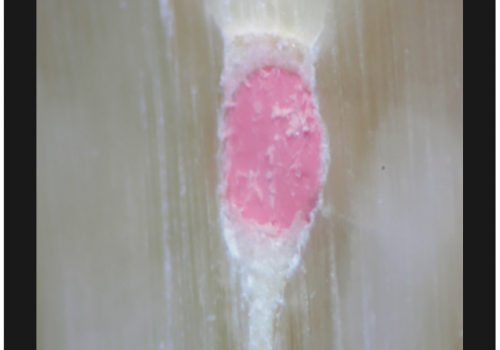
| Figure 5. The mesial root graphic, outlined in blue, was derived from the following measurements: 0 mm to 0.20 mm, 1 mm to 0.35 mm, 2 mm to 0.41 mm, 3 mm to 0.47 mm, 4 mm to 0.53 mm as determined by Dr. Barnett to be the optimal ACZ shape achievable with the K3 system. The distal root graphic uses zero mm to 0.25 mm as the starting point. | Figure 6. Tooth No. 4.6 (30) demonstrates the degree of obturation density and flow characteristics typical of the optimal rheology achievable with a well-shaped ACZ (courtesy of Dr. Fred Barnett). |
Once the K3 files (Figures 4a and 4b) have reached the electrometrically determined working length, the clinician needs to determine the appropriate degree of apical enlargement for each canal. Final apical gauging can now be accomplished with a series of stainless steel hand files. If, for example, the final apical gauging procedure allows for a size No. 35 hand file to be placed to the WL, it may be prudent to take the No. 35/0.06 K3 rotary file to length. This will create a continuous taper from orifice to constriction. If the root is thin and/or if the canal is moderately to severely curved, a K3 No. 35/0.04 rotary file taken to length may be more appropriate. The Apical Control Zone is created by stepping back in 0.5-mm increments with either the 0.04 or 0.06 tapered K3 files (Figures 5 and 6). This technique can be viewed on the Internet at k3endo.com.
THE LIGHTSPEED ACZ TECHNIQUE (LightSpeed Technology Inc)
 |
 |
| Figures 7a and 7b. To create the ACZ, begin with the suggested First LightSpeed Size to Bind. Using moderate force, advance the FLSB to WL. If it goes to WL, it means the canal is larger than this size. Try sequentially larger sizes until one binds. If the suggested FLSB doesn’t go to WL (binds), try sequentially smaller instruments until one does go to WL. |
Straight-line endodontic access preparation is initiated, and the coronal third of the root canal space prepared with an instrumentation protocol of the operator’s choosing (Figures 7a and 7b). The apical foramen is located with an EAL and working length established; (WL) 0.25 mm to 1 mm short of the foramen (practitioner’s choice). Note that for the ACZ graph in Figure 7a, a WL was chosen that is 0.25 mm from point zero for the size 40 LS, and a WL that is 0.50 mm from point zero for the size 50 LS.
 |
 |
| Figure 8. Size Nos. 20 to 60; the cutting-edge diameter of the LightSpeed instrument varies sequentially by an increase of .025 mm. From size Nos. 60 to 70, the variability is 0.05 mm, from 70 to 100 the sizes increase by 0.10 mm. | Figure 9. The LightSpeed system ensures that the integrity of the tooth structure is not compromised regardless of the degree of curvature of the root canal system (courtesy of Dr. William Wildey). |
Canal patency is ensured to the WL with at least a size 15 K-file. Rotary instrumentation is initiated with the smallest LS size that binds on the canal walls before it reaches WL when advanced apically by hand (Figure 7b). Mechanical preparation to WL begins with the smallest LS file that binds and continues with sequentially larger sizes (Figure 8). The final apical preparation size is determined using the “12 pecks” rule. This rule ensures the canal is instrumented to a large-enough size to ensure optimal canal debridement.22 This technique can be viewed on the Internet at LightSpeedUSA.com. The ACZ for LightSpeed is based on an apical stop (dentinal matrix) preparation. In Figure 7a, the operator-created AC or point zero was chosen to be a No. 20 file for the mesial canals and a size 25 for the distal to standardize the procedural formats. The preferred apical preparation size for the mesial canals is a size 40; therefore, on the graph, point zero would be a size 20, and 0.25 mm from point zero the preparation would be a size 40. It remains parallel (size 40) to the end of the graph (4 mm). The suggested apical preparation size for the distal canal is usually a size 50. Therefore, on the graph, point zero would be a size 25, and 0.50 mm from point zero the preparation would be a size 50. It would remain parallel (size 50) to the end of the graph (4 mm). In an actual case, enlargement is based on the original anatomy (diameter) of the canal in the ACZ. With experience, tactile feedback from LightSpeed’s unique design will give the practitioner a very accurate means of determining when the canal has been instrumented to the proper diameter. Estimates of canal preparation diameters in the ACZ are provided based on clinical and research statistics (Figure. 9).
THE RACE ACZ TECHNIQUE (Brasseler USA)
 |
| Figure 10. The RaCe NiTi rotary file system. |
Straight-line access preparation is established and debridement of the coronal aspect of the root canal space is initiated with a No. 25/0.06 instrument. This file is effective in opening the orifice, eliminating the cervical dentinal ledge, and removing the bulk of coronal pulp tissue (Figure 10). The No. 25/0.06 file can generally be taken half to two thirds of the way down the canal. The clinician is thus able to feel the presence of coronal or midroot curvatures. Furthermore, it removes sufficient tissue to prevent the creation of a tissue plug that characteristically occurs with SS hand files when coronal pulp is pushed apically and compacted. Working length is established with an EAL using a NiTi rotary file or stainless steel hand file.
 |
 |
| Figure 11. The mesial root graphic, outlined in blue, was derived from the following measurements: zero mm to 0.20 mm, 1 mm to 0.26 mm, 2 mm to 0.32 mm, 3 mm to 0.38 mm, 4 mm to 0.44 mm. The distal root graphic was derived from zero mm to 0.25 mm, 1 mm to 0.31 mm, 2 mm to 0.37 mm, 3 mm to 0.43 mm, 4 mm to 0.49 mm. | Figure 12. The elegance of the flow characteristics of the RaCe system is demonstrated in tooth No. 3.6 (18). |
When minimal coronal curvature is detected with the scouting No. 25/0.06, the No. 40/0.10 is used to remove additional coronal dentin. A No. 25/0.02 is taken to length or until more apical pressure is required to make apical progress than was required for the first millimeter of engagement. With the No. 25/0.02 instrument to length, a No. 25/0.08 is advanced as far as possible. The No. 25/0.04 is generally taken to length, followed by the No. 25/0.06 to length. If the No. 25/0.06 will not go to length, the No. 25/0.08 or No. 40/0.10 is used to remove more coronal dentin. With a No. 25/0.06 to length, the majority of cases have an apical control zone ideally suited to thermo-softened obturation (Figure 11). In distal or palatal roots, it may be possible to take the No. 25/0.08 to length. A No. 35/0.02 can be taken to length should apical gauging indicate a larger apical diameter is required (Figure 12).
THE PROTAPER ACZ TECHNIQUE (DENTSPLY Tulsa Dental)
 |
| Figure 13. The mesial root graphic, outlined in blue, was derived from the following measurements: zero mm to 0.20, 1 mm to 0.27, 2 mm to 0.34, 3 mm to 0.41, 4 mm to 0.46. In the distal root, the F2 (0.25/0.08) carried to WL was used as the standard. |
Root canal preparation procedures are optimized when there is straight-line access to the orifice(s). The ProTaper shaping technique begins by first negotiating the coronal two thirds of a canal with Nos. 10 and 15 hand files, which are utilized within any portion of a canal until they are loose and a smooth, reproducible glide path is confirmed.23 The depth of insertion of the No. 15F is measured, and this length transferred to shaping file No. 1 (purple ring) and shaping file No. 2 (white ring), which are termed S1 and S2 respectively. The secured portion of the canal can be optimally pre-enlarged by first utilizing S1 then S2 (Figure 13). The auxiliary shaping file, or SX, may be used to relocate the coronal aspect of canals away from external concavities and to produce more shape within any canal, as desired. Without pressure, and in one or more passes, each ProTaper shaping file is allowed to passively cut into the canal until its apical travel slows, then it may be used like a brush to laterally cut dentin on the outstroke until this region of the canal is optimally prepared.
 |
 |
| Figure 14. The current iteration of the NiTi ProTaper rotary instrument series is comprised of just 3 shaping and 3 finishing instruments. ProTaper hand files are in development as are accessory rotary files for larger canals. | Figure 15. This endodontically treated maxillary molar demonstrates that the Protaper system can safely shape the complexities of the apical one third of the most traditionally difficult canals (courtesy of Dr. Yosef Nahmias). |
When the coronal two thirds of the canal is prepared, the apical extent of the canal is then fully negotiated, working length confirmed, patency established, and the foramen enlarged to at least a size 15 hand file.24 If a smooth, reproducible glide path to the terminus is verified, the S1 and then the S2 are taken to the full working length. Following the use of the shaping files, working length should be reconfirmed as a more direct path to the terminus has been established. Three ProTaper finishing files termed F1, F2, and F3 have yellow, red, and blue identification rings corresponding to D0 diameters/tapers of 0.20/0.07, 0.25/0.08 and 0.30/0.09 respectively (Figure 14). Depending on the length, diameter, and curvature of the canal, the F1 will generally achieve length in one pass. The finishing criterion is to remove the F1, inspect its apical flutes and, if they are loaded with dentin, the shape is cut. To confirm the size of the foramen, gauge with a No. 20 hand file. If the No. 20 hand file is snug at length, then the ACZ is fully shaped and, if irrigation protocols have been followed, ready to pack. If the No. 20 hand file is loose at length, proceed to the F2, and when necessary, the F3, gauging after each finisher with the 25 and 30 hand files respectively. The ProTaper sequence is always the same regardless of the tooth or anatomical configuration of the canal being treated. In many cases, it’s as easy as 1-2-3, or in endodontic language, purple-white-yellow (Figures 14 and 15). Further information on ProTapers can be viewed at endoruddle.com.
THE PROSYSTEM GT ACZ TECHNIQUE (DENTSPLY TULSA DENTAL)
As with other systems, rotary shaping files must have straight-line access into the root canal space and should not be used until patency has been established with a No. 10 k-file at least 1 mm past the terminus of the canal. Straight-line access is easily accomplished using the GSRoots Access Bur Kit (Obtura/Spartan).
 |
| Figure 16. The graph on the right illustrates the ACZ created by using a GT file 20/0.08 taper. This file is used to provide the ideal shape in smaller canals. On the left, this graph shows the use of a GT file 30/0.08 that can be used to create an ideal ACZ in larger canals such as a distal canal of a lower molar. Note that the GT system produces predetermined shapes in contrast to operator-machined shapes using the step-back approach. As in the Protaper system, the files create the shapes, not the operator. |
Crown-down shaping always starts with the 20-.10 GT file, regardless of root size, and continues in a crown-down fashion until the first GT file gets to length (20-.10, 20-.08, 20-.06 or 20-.04). As a general rule, small roots (mandibular incisors, 2- and 3-canal premolars, mesial roots of lower molars, and buccal roots of upper molars) are shaped to a 0.06 or 0.08 taper or to a 0.04 taper in canals with abrupt apical bends or multiplaner curves. Medium roots are distal roots of lower molars and palatal roots of upper molars and usually have a 0.10 taper. Large roots are lower cuspids, upper anteriors, and 1-canal premolars.25,26 These roots usually require a 0.10 taper, but can also require 0.12 tapered accessory instruments (Figure 16). Increase the taper in the canal to the shaping objective file. This technique can be viewed on the Internet at endobuchanan.com
K-files are used to gauge the terminal diameter. The function of apical gauging is to measure the apical diameter of the canal after the shaping objective file has been cut to length. This is necessary to confirm that apical continuity of taper exists and that the tapered preparation extends all the way to the terminus of the canal. The shaping objective file taken to length has a 0.20-mm tip diameter; gauging is done with a No. 15 file passed through the canal terminus. A No. 20 k-file is taken to the terminus without pushing or cutting dentin. If it lightly binds at length, and the No. 25 and 30 files bind shorter in the canal, there is apical continuity, and the shape of the canal has been determined. If the No. 20 k-file can still pass through the end of the root canal without meeting resistance, the k-file that binds at length is determined, and the shape is adjusted by taking the same-size tapered instrument into the canal with a larger tip size—either a 0.30-mm or a 0.40-mm GT file.
 |
 |
| Figure 17. The ProSystem GT NiTi file system features an extensive array of rotary as well as hand files. | Figure 18. The obturation of this maxillary molar demonstrates the uniformity of the smooth tapered multiplanar shapes possible with the ProSystem GT (courtesy of Dr. Ken Serota). |
GT files provide a level of forgiveness with regard to length determination errors. As in the case of the ProTaper system, the ProSystem GT files are designed to create a predetermined ACZ (Figures 17 and 18).
CONCLUSION
The authors of this article are all members of the endodontic cybercommunity ROOTS (roots@ls.rxdentistry.com). Its daily goal is to raise the bar on endodontic education and the means by which that education can be delivered with unprecedented speed, accuracy of content, and the facility for dialogue. The membership was polled for the creation of this article and several trends were evidenced from the responses…
(1) Tapered apical preparations were the norm; the range in taper varied from 0.06 to 0.20 mm or greater.
(2) Thermolabile obturation predominated.
(3) Patency was a primary objective in the majority of the treatment protocols.
(4) Electrometric devices were used in virtually 100% of treatment. Many of the respondees do not use WL x-rays, and some use paper points for length confirmation.
(5) The creation of an Apical Control Zone was technique-dependent—it was not a priority for all practitioners; however, it was used by most in wide canals/open apices.
With vision, patience, an open mind, and the ability to assimilate—and by combining evidence-based science, clinical empiricism, and technical acumen with the transactional capacity for 3-dimensional perception—the successful outcome of any endodontic procedure has never been more attainable. And this is just the beginning of the era of the “NiTi Jamboree.”
Note: The ACZ images can be viewed in Shockwave animation at endosolns.com (go to “For the Dentist,” and then to “Library.”).
Acknowledgment
The authors would like to thank Drs. L. Stephen Buchanan, John McSpadden, Paul Bery, and Clifford J. Ruddle for their assistance in the preparation of this manuscript.
References
1. Walia HM, Brantley WA, Gerstein H. An initial investigation of the bending and torsional properties of Nitinol root canal files. J Endod. 1988;14:346-351.
2. Dalton BC, Orstavik D, Phillips C, et al. Bacterial reduction with nickel-titanium rotary instrumentation. J Endod. 1998;24:763-767.
3. Pettiette MT, Metzger Z, Phillips C, et al. Endodontic complications of root canal therapy performed by dental students with stainless steel k-files and nickel-titanium files. J Endod. 1999;25:230-234.
4. Schilder H. Cleaning and shaping the root canal. Dent Clin North Am. 1974;18:269-296.
5. Mullaney TP. Instrumentation of finely curved canals. Dent Clin North Am. 1979;23:575-592.
6. Marshall FJ, Pappin J. A Crown-down Pressureless Preparation of Root Canal Enlargement: Technic Manual. Portland, Oregon: Dept of Endodontics, Oregon Health Sciences University; 1980.
7. Goerig AC, Michelich RJ, Schultz HH. Instrumentation of root canals in molar using the step-down technique. J Endod. 1982;8:550-554.
8. Roane JB, Sabala CL, Duncanson MG Jr. The “balanced force” concept for instrumentation of curved canals. J Endod. 1985;11:203-211.
9. Roane JB. Balanced force, crown-down preparation, and inject-R Fill obturation. Compend Contin Educ Dent. 1998;19:1137-1149.
10. Ingle JI. A standardized endodontic technique using newly designed instruments and filling materials. Oral Surg. 1961;14:83-91.
11. Morgan LF, Montgomery S. An evaluation of the crown-down pressureless technique. J Endod. 1984;10:491-498.
12. Fava LR. The double-flared technique: an alternative for biomechanical preparation. J Endod. 1983;9:76-80.
13. Torabinejad M. Passive step-back technique. Oral Surg Oral Med Oral Pathol. 1994;77:398-401.
14. Reddy SA, Hicks ML. Apical extrusion of debris using two hand and two rotary instrumentation techniques. J Endod. 1998;24:180-183.
15. Ferraz CC, Gomes NV, Gomes BP, et al. Apical extrusion of debris and irrigants using two hand and three engine-driven instrumentation techniques. Int Endod J. 2001;34:354-358.
16. Machtou P. Endodontic canal preparation: advances in rotary instrumentation. Pract Periodontics Aesthet Dent. 1998;10:937-940.
17. Serota KS, Glassman GD. Root canal preparation using engine-driven nickel titanium rotary instruments. Pract Periodontics Aesthet Dent. 1999;11:1117-1122.
18. Sabala CL, Biggs JT. A standard predetermined endodontic preparation concept. Compendium. 1991;12:656-660.
19. Dovgan JS. Incorporating nickel titanium instrumentation into your practice. Dent Today. 1998;17:86-93.
20. West JD, Roane JB. Cleaning and shaping the root canal system. Pathways of the Pulp. 7th ed. St. Louis, Mo: Mosby; 1998.
21. Glassman GD, Serota KS. A predictable protocol for the biochemical cleansing of the root canal system. Oral Health. July