Once the dentist has determined that the treatment of choice for the replacement of missing teeth is a removable partial denture, it is his or her responsibility to fabricate a prosthesis that will function as close as possible to natural teeth and not contribute to the continued loss of the remaining dentition.
First and foremost, a removable partial denture (RPD) should function to masticate food properly for digestion, aid in speech, improve aesthetics and facial form, and minimize deleterious forces placed on the supporting structures of the mouth (ie, abutment teeth, gingival tissues, alveolar bone, tongue, and buccal mucosa). Secondly, the RPD should be designed to maximize comfort for the patient. Only after the RPD is designed for function and comfort can we consider the aesthetics as our next criterion. Although very important, aesthetic considerations should not be placed before function and comfort in order to create a successful removable prosthesis.
Finally, RPDs should be designed to adapt to the dynamic conditions present in the oral cavity. A well-conceived RPD should be designed with built-in permanence in mind. That is, it should be constructed so it can easily be repaired and adapted to possible tooth loss in the future without compromising function, comfort, and aesthetics.
The evolution of RPDs has followed a flawed pathway leading to a myriad of designs that have essentially failed the dental profession and ultimately the dental patient. This history of failure is based on the fact that the vast majority of RPDs do not function to protect or preserve abutment teeth and strengthen the surrounding periodontal structures. They are not usually comfortable or aesthetically pleasing.
To understand why, after all this time, this problem is so common in our profession, we must understand the inner workings of a RPD. We must recognize that RPDs are machines, and ask ourselves, “How does our machine work?” Not until we understand the components of our machine can we attempt to design it properly for use. In physics, simple machines fall under 6 classifications: the wheel and axel, the inclined plane, the screw, the pulley, the wedge, and the lever.1
Essentially, removable partial dentures are levers. With this in mind, we can appreciate that an ideal, efficiently built lever will maximize its capabilities and multiply its effort through a fulcrum into its resistance arm, and move an object with increased force. In the case of RPDs, an efficiently built prosthesis would efficiently torque teeth. Herein lies the inherent path to failure: the efficiency of the lever. For RPDs to succeed in the long term they must be built as inefficient levers incapable of producing efficient torque force.
 |
|
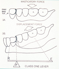
Figure 1. Schematic drawing showing class I lever in clasp design for a removable partial denture. Note: E = effort arm; F = fulcrum; R = resistance arm. |
Historically, RPDs have divided along their development into 2 basic schools of thought. One path has been based on a highly efficient class I lever system used during function and at rest2 (Figure 1). By the laws of physics, this philosophy of design, no matter what variations one may add, will impose excessive horizontal forces to abutment teeth during function, leading to mobility and potential loss.3,4 An example of an efficient class I lever is a crowbar that moves a heavy object utilizing a fulcrum that magnifies force through an effort arm into a resistance arm. At rest, when the prosthesis needs retention, it is not capable of retaining without creating excessive force on the tooth or clasp itself. Efficient class I lever RPDs with their built-in faults have spawned an unlimited “hodge-podge” of partial denture designs. Because of their inherent lack of stability during function and lack of retention at rest, they require excessive metal clasping that tries to compensate for these problems. This leads to unsightly clasping that is prone to breakage, along with trauma to the supporting structures. This leaves the RPD based solely on efficient class I lever principles as a blind science with no true laws or rules of design, yielding deleterious noncosmetic prostheses that should be regarded as part of a bygone era.
 |
|
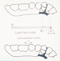
Figure 2. Schematic drawing showing class II lever in clasp design for a removable partial denture. Note: E = effort arm; F = fulcrum; R = resistance arm. |
The other path of removable prosthetics is based on incorporating the class II lever system of physics for retention during the dislodging motion only2 (Figure 2). This concept of design will dramatically decrease horizontal torque forces. For the most part, although far more protective to abutment teeth, class II lever RPDs are limited in design unless we adapt the teeth to conform to the necessary control of vector forces.
In order to accomplish this, correctly designed RPDs must utilize proper tooth preparation. Tooth preparation allows room for adjacent rest seats and guide planes so as not to interfere with occlusion. For control of the vector force, proper placement of the retentive clasp must be equal and opposite in both the vertical and horizontal planes to the prepared rest and adjacent guide plane. This will minimize the efficiency (less torque) of the lever and provide for aesthetic designs that show little or no metal while maximizing stability during function and retention at rest. Proper tooth preparation also enables adaptation of the RPD to the vast array of possible remaining tooth configurations we encounter. With proper tooth preparation we can offer the patient long-term care for a much broader range of problems.
Enamelplasty has been proven safe.5 Prepared enamel surfaces can be polished to less than 15 microns and resist decay.6 Decay is a function of bacteria and the presence of a food source. Dental prosthetics do not cause decay; poor hygiene is the culprit. With the availability of fluoride rinses and toothpastes, ultrasonic and rotary toothbrushes, floss, and access to dental care, there is little excuse for poor hygiene except neglect.
A restoration may be placed to house the rest preparation, if necessary. This may be as simple as an amalgam or as substantial as a crown. It is better to prepare teeth to direct forces than not to prepare teeth and allow traumatic torque forces that will lead to the eventual loss of teeth.
Perhaps the greatest criterion for enabling a RPD to function properly and be comfortable is its requirement to be stable during function as well as at rest. Stability is defined as resistance to movement in the horizontal, vertical, and rotational planes. Factors that contribute to RPDs being stable include properly designed rests and guide plates, coverage of retromolar pads, coverage of tuberosities, palatal design, and proper extension of flanges.
In order for a RPD to be stable it must utilize a tooth-borne framework, especially in free-end saddle design.7 Once we deviate from a tooth-borne scenario and rely solely on a tissue-borne prosthesis for aesthetics, we greatly compromise the stability and protective capabilities that a tooth-borne appliance can offer. Removable prostheses that prioritize aesthetics before function and comfort will leave the patient wearing the appliance out of necessity or not at all.
The use of guide plates may be the least appreciated component of a well-designed RPD. The guide plate, along with an adjacent rest, acts as a fulcrum to direct forces along the long axis of abutment teeth.8 It stabilizes the appliance from horizontal and rotational movement during function and provides indirect retention during dislodging while at rest.9
 |
|
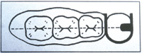
Figure 3. Schematic drawing of intra-arch configuration in the design of a RPD. Note: All components of the lever (effort arm = denture base; fulcrum = rest; resistance arm = back action clasp) are in a straight line over the height of the ridge. |
An inefficient lever will exhibit the greatest amount of stability and the least amount of torque when all the components of the lever (effort arm, fulcrum, and resistance arm) are intra-arch in configuration and as close as possible to a straight line2 (Figure 3). In addition to designing an inefficient lever RPD with intraarch configuration, we must utilize balance of force principles10 formulated by Sir Isaac Newton in the 17th century. This will aid in protecting and preserving abutment teeth and strengthening the surrounding periodontal tissues. Newton stated, “For two forces acting on a particle to be in equilibrium, the forces must be equal and opposite.”1
This must come into play in the proper design of clasping abutment teeth. During rest, when the inefficient class II lever component of a RPD tends to dislodge, the clasp should be made to engage a prepared undercut that is equal and opposite in the horizontal and vertical planes to the indirect retention of the guide plate.10 When inefficient class II lever clasps engage properly prepared undercuts during dislodging motions and are reciprocated 180° or more with guide plates, they are very close to being equal and opposite in force. This balance of force limits the torque on the abutment tooth and thereby acts to protect and preserve it. It should be noted that since the clasp engages only when the partial is at rest, the magnitude of the force (weight of the partial denture) transmitted to the clasp is minimal. During function, the clasp in a class II lever moves away from the undercut, and no torque force is transmitted through it to the tooth.7,11
The efficient class I lever retains itself during function. Stability and retention occur at the same time (during function) and work against each other. The forces of mastication, magnified by the class I lever, are transferred to the clasp, and a horizontal torque force of great magnitude is transmitted to the tooth, and destructive forces are transmitted to the periodontal structures. The tighter the clasp is for retention, the more efficient it is at directing its leveraging force into moving the tooth laterally.
To reduce this mechanical leverage we must separate stability from retention. To create a removable partial denture that is highly inefficient in producing torque during function and at rest, yet highly stable during function and retentive at rest when it is needed, we must build a framework that uses inefficient class I lever design during function and inefficient class II lever design at rest. This will separate stability and retention.
The least efficient way to build a class I lever partial denture and minimize its torque capability is to minimize the size of its lever arms. In the case of a RPD, we cannot minimize the effort arm because this is predetermined by the area of missing teeth. The effort arm is the area of the saddle and denture teeth. We can, however, minimize the resistance arm in the class I lever by utilizing a guide plate that runs completely from buccal to lingual on a tooth opposite the side of the effort arm. We do not need retention to chew food when the prosthesis is functioning as a class I lever. With a minimal resistance arm for horizontal force, most of the force will be directed through the fulcrum vertically along the long axis of the tooth. It is built with only a guide plate and adjacent rest for stability, therefore it is inefficient in producing torque during function.
This same framework should also incorporate a class II lever for retention, only when the prosthesis is at rest and not functioning to chew. It only utilizes the class II lever component to hold it in the mouth when the partial is at rest. The efficiency of the class II component of the design is minimized by the mere fact that the amount of force (weight of the partial) being magnified from the effort arm (denture base) through the fulcrum to the resistance arm (clasp) is minimal. Enough force is not generated to stress the abutment teeth and periodontal structures.
If abutment teeth are compromised structurally and crowns become a necessary component of the RPD design, then it is imperative to design the crowns with the same considerations as natural abutment teeth. They must conform to the properly designed inefficient lever framework to guide forces along the long axis during function and work in conjunction with the balance of force principles of clasp design. They must conform to the philosophy of protecting and preserving abutment teeth and strengthening periodontal structures. With this in mind we can eliminate all extra-coronal attachment crowns from our designs. All extra-coronal attachments are cantilevers that create torque on teeth. They lead to bulky, anatomically incorrect crowns that must be splinted to other teeth in free-end designs. If there were ever an example of sacrificing teeth unnecessarily, it would be the multiple splinting of abutment teeth for the sake of using extra-coronal attachments.
Intra-coronal attachments and crowns with prepared rest seats are the treatment of choice. These intra-coronal designs must follow strict guidelines. They must require normal tooth preparation. There must be no over-prepping of teeth to accommodate the attachment. All rest seats and attachments must conform to inefficient RPD framework design that separates stability and retention.
To prevent the need for multiple splinting of abutment teeth in free-end designs, the abutment crown must incorporate all the principles of inefficient lever physics, intra-arch configuration, and balance of force principles of clasp design. If these guidelines are followed just as in natural teeth, single abutment crowns can be used successfully with long-term prognosis.
It has been documented that the dental profession has had little success in finding a simple, predictable, and reliable RPD system. National studies have shown that patients are rarely satisfied with the function, comfort, and aesthetics of traditionally designed RPDs.12 With a well-conceived RPD system based on inefficient lever design that separates stability and retention, intra-arch configuration, and balance-of-force principles, stable and comfortable RPDs can be delivered to the patient, and the preservation of abutment teeth can be maintained with long-term results.
CASE REPORT
 |
 |
|
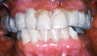
Figure 4. Preoperative photo of patient showing extensive breakdown of existing dentition, including periodontal structures, decay, a fistula on tooth No. 9, and missing teeth. |
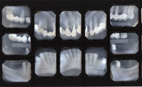
Figure 5. Preoperative full-mouth series of radiographs. |
This case involves the fabrication of an upper and lower RPD and supporting crowns based on the above guidelines for an inefficient lever design.
A 72-year-old female patient presented with many missing teeth and existing fixed bridgework that had failed due to recurrent decay (Figures 4 and 5). Due to financial limitations, implants were not an option for replacing her teeth. The remaining tooth configuration did not allow for fixed bridgework (either no posterior abutment teeth or large edentulous spans between abutments were present). Removable partial dentures were the only viable alternative for reconstruction. The patient requested to have the RPDs fabricated so that aesthetics would be maximized. She did not want “unsightly clasps.”
 |
 |
|
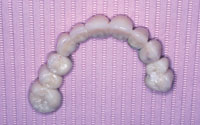
Figure 6. Reinforced acrylic provisional fixed bridge used as temporary restoration for teeth Nos. 3 to 13. |
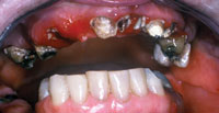
Figure 7. The condition of the patient’s teeth immediately after removing the existing fixed bridgework. |
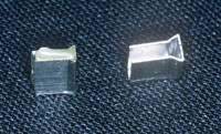 |
| Figure 8. Components of the Equipoise C-rest. Male on the left (this is cast to the framework of the partial denture); female on the right (this is soldered into the fixed bridge or crown). Archive photo courtesy of Equipoise Dental Consulting. |
 |
 |
 |
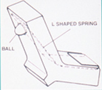
| Figure 9. A schematic drawing of the Equipoise L-Spring showing its component parts and its relation to the partial denture framework. |
 |
 |
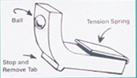
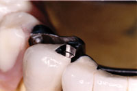
| Figure 10. Photo shows an example of a male C-rest on a partial denture as it seats into the female counterpart of a fixed restoration. Also visible is the retentive ball of the L-Spring, which is in its protective housing in the partial denture framework. The L-Spring is replaceable chairside and is designed to wear down before causing wear on the crown. (Archive photo courtesy of Equipoise Dental Consulting.) | Figure 11. Photo of the Equipoise clasp assembly. This photo shows an example of a plate and rest with a back action E-Clasp for tooth No. 28. Also pictured is an additional plate and rest for tooth No. 27. Double plating is used in periodontal splinting cases. (Archive photo courtesy of Equipoise Dental Consulting.) |
Radiographs were analyzed and a treatment plan was formulated. The primary treatment included determining which of the teeth were hopeless and required extraction, which teeth required periodontal treatment including surgery, which teeth might need endodontic therapy, and which required immediate treatment, ie, caries control. Once the diagnostic phase revealed which teeth would be salvaged, a reinforced acrylic fixed bridge to be used as a temporary maxillary restoration was made in advance from diagnostic models (Figure 6).
After removing the existing fixed bridgework (Figure 7) and all extractions were completed, the interim fixed bridge was cemented with a temporary cement (Temp-Bond [Kerr]). Periodontal treat-ment was completed, and the tissues were given appropriate time to heal.
To ensure the best possible prognosis for the patient’s few remaining teeth, RPDs based on inefficient lever design were chosen. The Equipoise RPD system (Equipoise Dental) was chosen because it is based on a full understanding of lever physics and engineering principles.
In the maxilla, teeth Nos. 3, 5, 11, and 13 were salvageable but would require crowns to restore them. To maximize aesthetics, an Equipoise precision C&L partial denture was fabricated. Equipoise offers 2 precision attachments that work in virtually all design configurations. The first is the Counterpoise (C-rest) stabilizer. It comprises 2 components, a male and female (Figure 8). The female is soldered into the crown; the male is cast onto the partial. The second attachment is the L-Spring retentive device (Figure 9). It is inserted into a cast housing on the partial opposite the side of the crown with the male C-rest. It is universal in size and shape and replaceable chairside (Figure 10). The Equipoise back action E-Clasp (Figure 11) can be substituted for the L-Spring retentive device when the L-spring cannot be utilized due to a lack of space or incompatible tooth position. All components of the Equipoise attachment mechanisms conform to balance-of-force principles by working equal and opposite in both the horizontal and vertical planes. They stabilize during function; they retain at rest.2
 |
 |
|
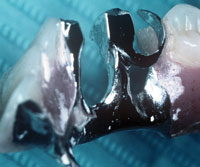
Figure 12. Photo showing the copings for the Equipoise crowns. Note: Teeth Nos. 5 and 11 have C-rest crowns; teeth Nos. 3 and 13 have conventional, Equipoise designed crowns. |
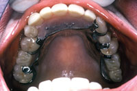
Figure 13. Photo showing framework for maxillary Equipoise partial denture. Note intra-arch configuration and minimal use of palate. Tooth No. 3 has an Equipoise conventional crown with a mesial guide plate, mesial-occlusal rest, and distal E-Clasp. Tooth No. 5 has an Equipoise C-rest crown with a mesial C-rest and distal E-Clasp. Tooth No. 11 has an Equipoise C-rest crown with a mesial C-rest and distal E-Clasp. Tooth No. 13 has an Equipoise conventional crown with a mesial guide plate, mesial-occlusal rest, and distal L-Spring. Crowns for teeth Nos. 3, 5, 11, and 13 are temporarily cemented at insertion. |
Crowns with precision mesial C-rests were made for teeth Nos. 5 and 11. On the distal would be contoured undercuts for the retentive device (Figure 12). The C-rest crowns offer maximum stability and longevity. Both the male and female components of the attachment are made of 10% iridium platinum and burnish equally with virtually no wear.2
Teeth Nos. 3 and 13 were restored with Equipoise contoured crowns. They incorporate mesial-occlusal spoon-shaped rests, mesial guide planes for stability, and contoured undercuts on the distal for the retentive device (Figure 12). The Equipoise contoured crown is based on the same principles as the precision C-rest crown except that a guide plane and rest seat substitute for the precision C-rest attachment. Both Equipoise contoured crowns and C-rest crowns will function to protect and preserve abutment teeth and strengthen periodontal structures.
The framework for the maxillary partial was cast in a rigid chromium cobalt (Niranium/CMP Industries) with E-Clasps for retention on teeth Nos. 3, 5, and 11 because of limited space; for tooth No. 13 an L-Spring retentive device was utilized (Figure 13).
 |
 |
|
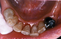
Figure 14. Photo showing coping try-in of single Equipoise C-rest crown on tooth No. 22. Tooth No. 28 has a mesial-occlusal composite restoration and shows use of separate, light-cured composite interproximally between teeth Nos. 27 and 28 acting as a space maintainer between visits. Note: This composite material is never bonded to either tooth and is easily removed and replaced by the dentist at each try-in visit. |
Figure 15. Photo showing tooth No. 28 with composite restoration that has a mesial-occlusal spoon-shaped rest preparation and a mesial guide plane preparation between teeth Nos. 27 and 28. Also shown is crown preparation for tooth No. 22. |
 |
 |
|
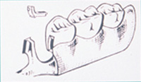
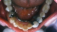
Figure 16. Photo of lower Equipoise partial denture framework (Note intra arch configuration). Tooth No. 22 has an Equipoise C-rest crown with mesial C-rest and distal L-Spring that is temporarily cemented at insertion. Tooth No. 28 has a mesial plate, mesial-occlusal rest and distal E-Clasp. |
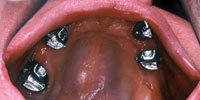
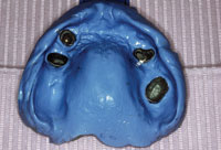
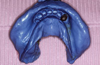
Figure 17. Photo of rigid pick-up impression of maxillary copings Nos. 3, 5, 11, 13 and simultaneous impression for upper partial denture framework. |
 |
 |
|
Figure 18. Photo of rigid pick-up impression of coping No. 22 and simultaneous impression for lower partial denture framework. |
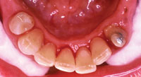
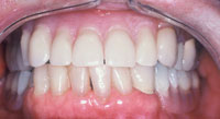
Figure 19. Five-year postoperative photo. Note: Abutment teeth and periodontal supporting structures are healthy. Case is highly cosmetic. |
In the mandible, teeth Nos. 22 to 28 were all saved. Tooth No. 22 needed a crown, and an Equipoise precision C-rest crown was chosen (Figure 14) because it is highly aesthetic and capable of acting as a freestanding crown to support a free-end saddle.2 Tooth No. 28 needed a composite restoration. A mesial-occlusal composite using Z100 (3M ESPE) was done (Figure 15). A light-cured composite, to act as a space maintainer, was placed in the area prepared for the guide plane between appointments (Figure 14). This prevents potential drifting of the adjacent teeth into this space. Due to the location of this tooth in the mouth, a conventional Equipoise clasp design (mesial plate, mesial-occlusal spoon-shaped rest, and distal E-Clasp) was used (Figure 16). Due to the minimal amount of metal in the interproximal plate, the patient was assured that this would be aesthetic.
All rest preparations and frameworks were designed with built-in permanence in mind. Each rest, guide plane, and retentive mechanism was placed so that if any teeth are lost over time the partial denture would be easily repairable and still function properly.
Once all tissues were healthy and the design finalized, crown preparations were done and impressions were taken (Extrude [Kerr]). Bite registration and vertical were established. Then, copings were tried in to check fit (Figures 12 and 14). A rigid pick-up impression of the copings and simultaneous impression of soft tissues was taken next (Extrude), so the upper and lower Equi-poise frameworks could be cast (Figures 17 and 18). Care was taken to incorporate retromolar pads on the mandible and the tuberosities on the maxilla.
At the next visit, the frameworks were tried in with the crown copings to check for fit and stability.
Bite and vertical were reconfirmed and a shade match was taken, along with the instructions for denture tooth morphology (mold guide for anterior teeth; occlusal plane for posteriors).
At the following visit, tooth set-up and shade match were confirmed. Any necessary refinements were made, and the case was sent back to the dental laboratory for denture processing and por-celain glazing.
At the insertion phase, crowns were cemented with temporary cement (Temp-Bond), and the RPDs were inserted (Figures 13 and 16). The patient was instructed in the insertion and removal of the prostheses. Proper oral hygiene was reviewed, and the patient was directed to reschedule in 48 hours. At that time no adjustments were necessary, and the crowns were cemented with permanent cement (Vitremer [3M ESPE]).
The patient was seen every 3 months for follow-up visits, including examinations and dental prophylaxis. A 5-year follow-up revealed no breakdown of abutment teeth from either decay or periodontal disease. The patient’s oral condition was improved and stabilized (Figure 19).
CONCLUSION
Removable partial denture