Despite the development of new and innovative instruments, techniques, and materials for cleaning, shaping, and obturation of root canal systems, obstruction of root canals by separated instruments, silver points, and metallic gutta-percha carriers blocking access to portions of the canal system remains a troublesome complexity.1-3 If the primary tenets of endodontic therapy—cleaning, shaping, and three-dimensional fluid-tight sealing of the entire canal system—cannot be achieved, the predictability of success declines markedly.4-6
While methods for obstruction bypass have been described,7 there are times when bypass is not possible or when complete removal of an obstruction is preferable to bypass. Although ultrasonic devices have proven to be very effective for removal of metallic obstructions from root canals,8-12 they have their limitations. Because of their tendency to create ledges and perforations and to lead to high-energy fractures13 of metallic obstructions, there are times when ultrasonic devices will prove to be ineffective and may even lead to greater complexity. Various hinged grasping devices such as Stieglitz forceps are standard instrumentarium for removal of obstructions that are accessible to these instruments—ie, obstructions with a component extending into the chamber. However, in cases where no portion of the obstruction extends into the chamber, other types of instruments and devices are necessary in order to remove the obstruction.
Many of these devices employ a metallic tube to receive the exposed aspect of the obstruction within the lumen of the tube, and then, by either friction14,15 or chemical bond,16,17 attempt to grasp and remove the obstruction. Because none of the previously available tubular grasping devices are easily bendable, their use is complicated in posterior teeth where inter-arch space is limited, and where prominent marginal ridges and cuspal morphology can impede direct access for a device of considerable length and tubular design.
 |
| Figure 1. The S.I.R. System kit contains 100 dead-soft bondable tubes of various internal diameters, a bottle of bonding agent, a bottle of accelerator, assorted instrument fulcrum props, and a curved hemostat. |
The introduction of a kit with various-diameter bondable dead-soft metal tubes to the field of obstruction removal devices provides an alternative with advantages over many of the currently available devices and systems. The S.I.R. (Separated Instrument Retrieval) System (Vista Dental Products) provides the operator with the ability to easily finger-bend the tubes to accommodate the specific insertion path in any particular case. Among the various elements included in the kit (Figure 1) are a specially formulated metal-to-metal bonding agent and a powerful accelerator that, when combined with each other, create a speedy, durable bond between the bendable tube and the obstruction.
 |
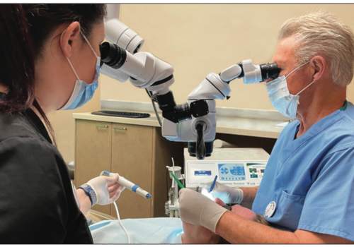
| Figure 2. High-powered fully-adjustable headborne system features up to 10X magnification, 6,000 foot-candles of coaxial fiber-optic illumination, and power-matched bridge-of-the-nose video camera. |
The use of dead-soft bonded metal tubes for deep obstruction retrieval operations as outlined below is considerably enhanced in every aspect by the use of high-powered visualization equipment (4X to 10X headborne system or microscope) and high-intensity coaxial illumination (4,000 to 6,000 foot-candles). The procedures described in this paper were all performed using a unique 10X/6,000 foot-candle headborne surgical telescope system with an integrated power-matched video camera (Figure 2) (Integrated Optics, CJM Engineering). Some of the clinical photographs represent digital video “frame-grabs.”
CASE STUDY
 |
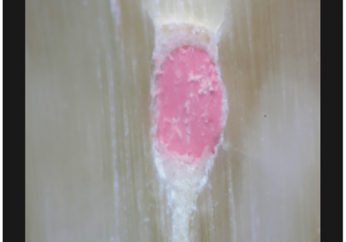
| Figure 3. A 3-mm segment of a No. 25K file separated beyond the orifice level in the MB2 canal. |
A 56-year-old female presented for examination and treatment of tooth No. 14, with a recent history of endodontic access and instrument separation in the MB2 canal. Radiographs revealed an instrument fragment of approximately 3 mm in length separated just beyond the orifice level in the MB2 canal (Figure 3). There was moderate curvature in the mesial root, and all canals were severely calcified.
Interestingly, the tooth gave a moderate-with-lingering response to ice. The tooth was very tender to percussion as well as to palpation over the MB root apex, with no evidence of swelling. There was a pre-existing MOD resin restoration with cavit in an endodontic access cavity. Periodontal probings were 2 to 3 mm 360°. Although previously accessed, a pulpal diagnosis of irreversible pulpitis was rendered (based on the ice test), and the periradicular diagnosis was acute apical periodontitis. Treatment recommendation was nonsurgical endodontic therapy preceded by separated instrument retrieval from the MB2 canal via dead-soft bonded tube. The anticipated complexities of treatment included separated instrument in the MB2 canal, severe calcification of all canals, and moderate curvature of the mesial canals.
Technique
Step 1. For deep retrieval operations, visual access to the most coronal aspect of the obstruction is essential. As such, it is often necessary to first expand the outline form of the standard endodontic coronal access cavity. In posterior teeth, this may require invasion of the mesial marginal ridge and/or the MB cusp area. Deep visual access may then be achieved by judicious application of extended-shaft (27 mm and/or 33 mm) slow- speed round burs and/or small Mueller burs, always recognizing where the bulk of root structure lies and where the structure is thinnest and at greatest risk of perforation. Removing structure from the areas of greatest bulk will not only reduce the risk of perforation, but will also generally provide the best line-of-site for visualizing an obstruction. The use of standard-length slow-speed round burs provides inadequate reach in most cases, and also draws the head of the handpiece into the clinician’s line of sight, totally obscuring the view of the working field.
Step 2. Once the coronal aspect of the obstruction is visible, if adequate space does not exist around the obstruction to accommodate the external diameter of the dead-soft tube that will be selected for the bonded tube removal process, space must be created. This may be achieved by very careful use of trephines or ultrasonic tips. Regardless of which instrument or combination of instruments is selected, the primary risks associated with creating space around metallic obstructions beyond the orifice level are the potential to create perforations, and the possibility of severing or weakening the exposed portion of the metallic obstruction, making an already difficult situation much more complex.
 |
 |
| Figure 4. A complete selection of trephines is essential for deep obstruction retrieval operations. | Figure 5a, 5b, and 5c. Selecting a slightly larger trephine reduces the risk of severing or weakening the obstruction while creating a dentin cylinder that can be easily removed with a Stewart probe or an ultrasonic tip. |
 |
 |
| Figure 5b. | Figure 5c. |
In using trephines (Figure 4), the purpose should not necessarily be to select the bur that will fit as closely as possible around the obstruction without actually cutting into it. Rather, a trephine should be selected that can be used safely within the amount of available root structure, circumscribing a cylindrical cut of dentin that may then be easily removed from around the obstruction with an ultrasonic tip or an explorer to expose more of the obstruction (Figures 5a through 5c). This could mean that, in cases of adequate root bulk, a size larger than the smallest trephine that slips over the obstruction might be the best selection (Figure 6) because it can reduce the risk of inadvertent weakening or severing of the obstruction. If the extraoral portion of the obstruction is available, it can assist in the selection of an appropriate trephine. Proper assessment of the angle at which the obstruction lies within the root structure is also essential in order to avoid cutting into the obstruction. Equally important is a working knowledge of the anatomy of the root so as to be able to safely “work into” the bulk of root structure if necessary. It is rarely advisable to use high-speed rotating instruments beyond the orifice level.
 |
| Figure 6. Selecting a tightly-fitting trephine (a) predisposes to weakening or severing of the obstruction. If bulk of root structure allows, a larger diameter trephine (b) should be selected. |
Ultrasonic tips provide certain advantages over trephines when creating space around an obstruction, but are also not without risk. The advantages are a great variety of tip angles, lengths, tapers, and diameters (Figure 7), providing useful options for many deep obstruction management operations. Unlike any other currently available hard-structure cutting instruments, ultrasonic devices provide virtually unobstructed visibility while in use deep within root structure because the head of the handpiece remains out of the line of sight as a function of tip geometry. Although the risk is measurably reduced when compared with rotating instruments, perforation still remains a liability when working with ultrasonic tips deep within root structure. Again, understanding the anatomy of the root as well as the orientation of the obstruction within the root will reduce perforation risk. The potential also exists for high-energy fracture of the obstruction, dislodging the exposed portion while leaving the more apical aspect lodged deeper within the root. Using a reduced energy setting and avoiding contact with the exposed portion of the obstruction while the ultrasonic tip is activated will reduce the risk of high-energy fracture. This is best achieved by the use of very tiny-diameter ultrasonic tips to trough around the obstruction under high magnification and enhanced illumination.
 |
 |
| Figure 7. A great variety of unique tip geometries provide unobstructed visibility of the activated tip while in use deep within root structure. | Figure 8. The S.I.R. System kit contains 100 bondable tubes in five internal diameters—18 ga, 19 ga, 20 ga, 22 ga, and 25 ga. |
Step 3. Once approximately 1.5 to 2 mm of the obstruction is exposed 360°, and the field has been thoroughly dried, an appropriately-sized dead-soft tube is selected from the five available diameters in the S.I.R. System kit (Figure 8). If the obstruction is a separated instrument, and the extra-oral portion of the instrument is available, the dead-soft tube may be “sized” by ensuring a close fit over the extraoral portion of the instrument (Figure 9). The lumen of a dead-soft tube may be slightly enlarged with 1/4, 1/2, 1, or 2 slow-speed round burs to more closely approximate the diameter of an obstruction. Magnification and enhanced illumination are very helpful for this lumen-enlarging process. The lumen may also be slightly decreased by gently squeezing the tip of the tube with a hemostat. The selected tube is then pre-bent and trial-inserted over the exposed portion of the obstruction in the canal. Several trial insertions at this stage will ensure a trouble-free final insertion (Step 6). The dead-soft feature of the tubes allows them to be easily bent to accommodate any insertion path. Once custom-bent, this tube is placed aside. It will be used to receive the bonding agent just prior to the final insertion.
 |
 |
| Figure 9. If the remainder of the separated instrument is available, it provides a convenient opportunity to “size” the appropriate tube from the five available diameters. | Figure 10. Agents are drawn into the tube by capillary action. |
Step 4. A single drop of Vista’s Prime-Set (Agent A), a highly active accelerator, is then placed onto a mixing pad. Using a second dead-soft tube of the same size as the one already selected, the agent is drawn into the tip through capillary action by simply touching the tip to the edge of the droplet of Prime-Set (Figure 10). The Prime-Set is then discretely applied to the obstruction by placing the tip of the tube over the exposed portion of the obstruction (Figure 11). This tube is then left in place until the tube with Quick-Set (Agent B) is ready to be placed (Step 6).
|
Table. Factors to Consider when Assessing Obstruction Management Cases A. Anatomic factors 1. Location and orientation of the tooth within the arch
•Tooth location—more posterior = more complex 2. Visual and physical accessibility through crown (while the following factors contribute to complexity with regard to isolation, they actually enhance deep visual and physical access)
•Gross coronal caries—access is enhanced when caries is removed 3. Nature of the root and the canal
•Shape of the root—thinner root = more complex due to risk of perforation 4. Location of most coronal aspect of obstruction in a straight canal
•Into chamber—bonded tube = no risk of ultrasonic fracture of obstruction 5. Location of most coronal aspect of obstruction in a curved canal
•Coronal to curvature—ultrasonics and/or bonded tube B. Obstruction-related factors
1. Dimensions of obstruction
•Length Longer fragment = greater adaptation to walls = more difficult to remove, and more susceptible to high-
energy fracture with ultrasonics
Shorter fragment = less adaptation to walls = easier to remove, and less susceptible to high-energy
fracture with ultrasonics
•Diameter
Larger diameter = greater wall contact = more difficult to remove, but less susceptible to high-energy
fracture with ultrasonics
Smaller diameter = less wall contact = easier to remove, but more susceptible to high-energy
fracture with ultrasonics
•Fluting or spiraling patterns of separated instrument
Deep flutes and spirals are bypassable (eg, GGs or Lentulos)
Clockwise or counter-clockwise fluting pattern, if discernable, determine extractive rotation
2. Metallurgical properties of obstruction C. Patient-related factors
1. Cooperation and compliance capacity of the patient (each factor below adds considerable complexity and tends to decrease the practical duration of any treatment visit)
•Limited opening
|
Step 5. A single drop of Vista’s Quick-Set (Agent B), a specially formulated metal-to-metal bonding agent, is then placed onto a mixing pad. It is important to use a separate mixing pad, or at least a separate page of the pad, to avoid premature activation of the Quick-Set by the accelerator. The Quick-Set is drawn into the cannula by capillary action when the selected dead-soft tube that was set aside in Step 3 is passed through the agent at a 45° angle in the same manner as described for Agent A in Step 4 (Figure 10).
Step 6. The tube containing the Prime-Set (Agent A) is removed from the obstruction where it has been since Step 4, and the tube now “charged” with Quick-Set (Agent B) is slid over the exposed portion of the obstruction in the root canal system. The accelerated bond starts immediately. There is very little opportunity for trial and error at the moment of insertion due to the powerful effect of the primer already present on the exposed portion of the obstruction. The trial insertions practiced in Step 3 will ensure reproducible proper grasp of the hub and orientation of the tube for a trouble-free final insertion. It is important to note that while the initiation of the bond is rapid, the maturation of the bond may take several minutes, during which time the “bonding system” must remain undisturbed to avoid interruption of the reaction.
 |
 |
| Figure 11. Prime-Set accelerator is discretely applied to the exposed aspect of the obstruction by slipping the tube over the obstruction and leaving it in place until the tube containing the bonding agent is ready to be placed (Step 6). | Figure 12. A vinyl autoclavable instrument prop (supplied) provides protection of the next anterior tooth, which is to be used as a fulcrum against which to “lever” the bonded tube and obstruction out of the canal. |
 |
 |
| Figure 13a, 13b, and 13c. Using the curved hemostat (supplied), the 3-mm long obstruction, now extended by virtue of the bonded 25-ga dead-soft tube, is “levered” out of the canal. | Figure 13b. |
 |
 |
| Figure 13c. | Figure 14. Once the obstruction has been retrieved, nonsurgical endodontic therapy can proceed as usual. |
Step 7. To create an effective fulcrum and to protect the next anterior tooth, an autoclavable instrument prop (supplied) is inserted over the next anterior tooth, the bonded tube is grasped with the curved hemostat (supplied) (Figure 12), and the dead-soft tube along with the now-bonded obstruction are “levered” out of the canal (Figures 13a through 13c).
Step 8. Nonsurgical endodontic therapy can now proceed as usual (Figure 14).
DISCUSSION
While many obstruction removal devices and techniques sound good in theory, look good on paper, and can in fact be very effective, they all have serious limitations and can rapidly degenerate to clinical failure in the absence of strict attention to protocol. Recognition of the limitations of instruments, techniques, and specific procedural steps is critical to the success of any obstruction management case. With that in mind, by judiciously following the steps outlined above, a high degree of predictable clinical success can be achieved in appropriately selected cases.
In evaluating obstruction management options, the dentist must first determine the level of complexity. The critical factors include anatomic and location issues related to the subject tooth, geometric and physical properties related to the obstruction itself, and patient-related issues such as opening capacity and overall cooperation capacity (Table).
The first anatomic consideration is often tooth location and orientation. Generally, the more posterior the tooth, the more complex the procedure by virtue of location, not to mention the increased anatomic complexity of canal systems in posterior teeth. The dentist must also consider interarch space (more critical with posterior teeth) relative to the various devices that may be necessary to use in removal or bypass operations. A tipped and/or rotated tooth presents visual and physical access complexities. The first actual physical barrier to obstruction access is usually the clinical crown. It goes without saying that the ability to achieve visual and physical access through coronal structure is absolutely essential. If caries, defective restorations, or coronal fracture do not already allow for unimpeded access, such access must be created by removal of structure.
In multicanal roots, the periorifice region should be carefully examined under high magnification and enhanced illumination to determine if an isthmus exists that can be exploited via ultrasonic tips and small slow-speed round burs (27- mm length) to enhance access to the obstruction. The mesial canals of molars are the most common canals involved in separated instrument mishaps. Fortunately, even in the absence of an isthmus, mesial roots of molars, both maxillary and mandibular, virtually always allow for removal of structure between the MB and ML canals to provide greater obstruction access. Similarly, in multi-canal premolars and the rare multi-canal canine tooth, structure between the canals can be removed to provide visibility and physical access to deep obstructions.
A keen awareness of external root contours is essential in order to avoid perforation when working deep within the root with slow-speed rotating instruments and ultrasonic tips. The nature of the canal as it surrounds the obstruction should also be carefully assessed under high magnification and enhanced illumination to determine if there is any chance of getting a “stick” with small files alongside the obstruction. Because the metallic obstruction will generally be regular in circumference, and canals are irregular, there is almost always at least one area where this “stick” can be detected—usually felt as a spot where a small-gauge file with a discreet bend at the tip will repeatedly stick alongside the most coronal aspect of the obstruction. This “sticky spot” can signal an opportunity to bypass, perhaps using a “file stiffening” procedure.
As a special discipline of healthcare, dentistry is comprised of some of the most extraordinarily creative and capable clinicians with regard to micromechanical problem solving. The introduction of dead-soft bonded tubes in the form of the S.I.R. System offers the savvy clinician another useful option for the management of one of the most complex clinical circumstances increasingly challenging d