When a patient consults a dentist because of some type of trauma to the face with pain in a specific region, making one suspect a fracture of the bone, one of the first procedures carried out is the taking of a radiograph of that area. When viewing the radiograph, it is important to be able to differentiate the normal radiographic anatomy from a possible fracture.
Radiographically there are four signs that can help the clinician when examining radiographs of patients suspected of having fractures. They are: (a) a linear lucent line; (b) a step in the cortex of the bone; (c) a change in morphology; and (d) an increase in opacity.
However, most linear lucent lines, steps, or apparent changes in morphology do not indicate fractures but sutures, margins of overlapping bones, or nutrient canals. An increased opacity may be seen when the sides of the fractured bone are superimposed. There are many anatomic structures that may mimic fractures and may be mistaken for a fracture in those cases where one is already suspected. Thus, it is essential that radiographic anatomy be known in detail. At the same time, it is essential never to attempt to make a diagnosis solely from radiographs. A basic requirement of radiographic interpretation of fractures is the need to have at least two projections taken at 90° to each other.
The aim of this article is to indicate some radiographic anatomy that may simulate the appearance of a fracture in the maxillofacial region.
MANDIBLE
Pharyngeal Air Space Versus Suspected Fracture of the Ramus of the Mandible
 |
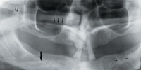 |
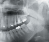
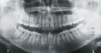
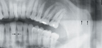
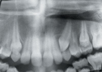
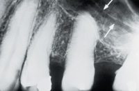
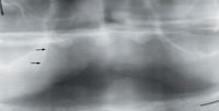
| Figure 1. Linear lucency (opposing arrows) seen on a panoramic radiograph and suggestive of fracture of ascending ramus of mandible. | Figure 2. a. The right coronoid process (two adjacent parallel arrows) has a linear, horizontal lucency suggesting the outline of a fracture. Immediately inferior to this line is the outline of the zygomatic process overlapping coronoid process. b. Panoramic radiograph showing an almost horizontal opacity of the hyoid bone in the middle of the right body of the mandible and indicated by the large arrow. c. The linear lucency (three adjacent arrows) inferior to the inferior concha and superior to the opacity of the hard palate simulating a fracture in the maxillary sinus. d. Two vertical linear lucencies (opposing arrows) in the left body of the mandible created by nutrient canals. |
 |
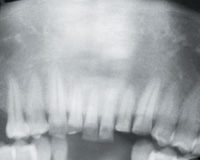 |
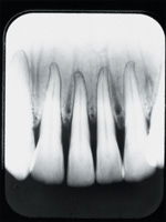
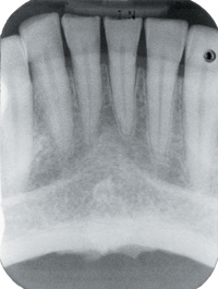
| Figure 3. Linear lucent lines seen in the mandibular anterior periapical radiograph mimicking the appearance of a fracture. Some nutrient canals can be seen ending in nutrient foramina. | Figure 4. Inferior border of C1 giving the appearance of an alveolar fracture inferior to the mandibular incisor teeth. The superior border of C2 is also visible. |
 |
 |
| Figure 5. a. Sutures in zygomatic arch bilaterally (single arrows). The lucency, the step, and the apparent change in morphology can be seen. b. Opposing arrows indicating linear lucency in maxillary sinus suggestive of a fracture. c. Adjacent arrows indicating overlapping of hyoid bone over body of mandible. d. Horizontal arrows indicating the outline of the head support over the ascending ramus of the mandible. |
Figure 6. a. A midline linear lucency (opposing arrows) seen in panoramic projection appearing between and above the apices of the central incisors. b. Double image of inferior border of contralateral mandible (adjacent arrows). |
 |
 |
| Figure 6c. Image of midline vertical lucency in maxilla as seen on a panoramic radiograph, appearing to extend to the floor of the nose. | Figure 7. Periapical radiograph of mandibular anterior region showing the mental ridge and the outline of the lower lip. |
 |
 |
| Figure 8. Periapical radiograph of maxillary posterior region showing a linear lucency (white arrows) in the maxillary sinus. | Figure 9. Panoramic radiograph of an older, edentulous patient showing the images of the nasolabial fold. |
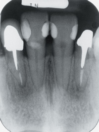 |
Figure 10. A periapical radiograph of the maxillary anterior region showing a horizontal lucency of the upper lip over the roots of both central incisors giving the impression of dental fractures. The midline, linear vertical lucency is visible as well between the central incisors. |
When taking a panoramic radiograph, it is essential to instruct the patient to place the tongue against the hard palate in the swallowing position and to maintain that position throughout the exposure. If this is not done, patients often double the tongue backwards creating an even larger pharyngeal air space. It is equally important to instruct the patient to maintain the elevated position of the tongue throughout the exposure time as patients often initially elevate the tongue but do not keep it elevated throughout the exposure (Figure 1).
The pharyngeal lucency may appear over the apices of the maxillary teeth obstructing the view of the apices of these teeth and may hide periapical pathology. The lucency may also continue or may only appear over
the ascending ramus of the mandible giving the appearance of a fracture in that area. A fracture will end at the cortical plates of the bone whereas the pharyngeal lucency usually continues anteriorly and/or posteriorly to the ramus. Where a fracture of the mandible is suspected, a postero-anterior projection should be requested.
Lateral Pterygoid Plate Versus Suspected Fracture of the Coronoid Process of the Mandible
The lateral pterygoid plate is a very thin bone that often does not attenuate the beam on its own and therefore is often not often seen on the panoramic radiograph. However, when the lateral pterygoid plate overlaps the coronoid process of the mandible, the beam is often sufficiently attenuated by the coronoid process for the edges of the pterygoid plate to be partly or totally visualized on the panoramic radiograph (Figure 2a). The outline of the plate often appears as a sharp, linear but irregular lucency overlying the coronoid process, giving the impression of a coronoid fracture. The coronoid process is protected by a muscular cushion, the temporal muscle and also by the zygomatic arch. Thus, fractures of the coronoid process constitute a very small percentage of fractures of the mandible. In most cases of fractures of the coronoid process, there is also a fracture of the zygomatic arch. Should a fracture of the coronoid process be suspected, in addition to the panoramic radiograph, a postero-anterior projection with the mouth wide open will clearly show the coronoid process.
Occasionally the lateral pterygoid plate overlaps with the zygomatic arch resulting in a similar appearance.
Nutrient Canals in the Mandible Versus a Suspected Fracture of the Mandible
Nutrient canals are not an uncommon finding in images of the mandible. They may be seen anywhere in tooth-bearing area but are more common in the anterior part of the mandible. They are seen on the radiograph as vertical, linear lucencies ending at the top of the alveolar ridge in the mandible and at the bottom of the ridge in the maxilla. The mandibular nerve divides into the mental and incisive nerves. Accompanying the nerves are blood vessels. The incisive nerve (and blood vessels) run forward in the bone giving off nutrient canals (vessels) and, in the area of the midline, anastamose with the incisive vessels from the contralateral side and then run upward close to the midline as nutrient canals.1 These lucencies are often so evident that they simulate fractures (Figures 2d and 3).
Cervical Vertebra Versus Suspected Mandibular Alveolar Fracture
If the patient is seated with the head/chin tilted too far down in the focal trough when a panoramic radiograph is being taken, the outlines of the cervical spines are sometimes seen very clearly. The inferior border of C1 or the superior border of C2, superimposed on the mandibular midline region, often gives the appearance of a horizontal, linear lucency indicative of a mandibular midline alveolar fracture. The lucency of the intervertebral disc space can be seen between the two opacities. If the patient is seated with the head too far forward in the focal trough, these outlines are often seen even more clearly (Figure 4).
Hyoid Bone Versus Suspected Fracture of the Body of the Mandible
The appearance of the image of the hyoid bone on a panoramic radiograph is very variable depending on the seating of the patient and the tilting of the neck. If the patient is correctly seated, the hyoid will be seen bilaterally, ending mesially inferior to the body of the mandible and approximately inferior to the first mandibular molar teeth. As the patient is seated further forward in the focal trough, the hyoid bone also moves further into the focal trough and becomes elongated. The further forward the patient is seated, the longer the appearance of the image of the hyoid bone, and this structure may appear to extend completely across the body of the mandible from one side continuously to the opposite side. The more the patient drops the chin, the higher the appearance of the hyoid bone. The elongated outline of the hyoid bone superimposed over the body of the mandible may give the appearance of a fracture of the body of the mandible with an increased opacity of the sides of the fracture. The increased opacity can be seen extending distally and inferior to the mandible, and this is the diagnostic clue (Figures 5c and 2b).
Panoramic Head Support Versus Vertical Fracture of Ascending Ramus of the Mandible
Many panoramic machines have a head support on either side of the face to assist in centering the patent during the exposure. The outline of the head support is seen on most of the images but sometimes appears so definite and with such a sharp outline as to be suggestive of a vertical fracture. Some clues in assisting the diagnostician are: the fact that an image of a fracture is never seen as a completely straight line; the appearance is often seen bilaterally; and the appearance extends inferior to the body of the mandible (Figure 5d).
Contralateral Double Image of the Mandible Versus Horizontal Fracture of the Body of the Mandible
When the patient is positioned in the panoramic machine with the chin raised or dropped only very slightly, the double image of the inferior border of the body of the contralateral mandible often appears and may give the appearance of an increased opacity simulating the sides of a fracture that are superimposed. This image is usually not seen if the patient is seated correctly or if the chin is raised or lowered excessively. The increased opacity is always situated superiorly to the line, and the line can be seen extending distally to the posterior border of the ascending ramus of the mandible (Figure 6b).
Mental Ridge Versus Suspected Fracture of the Anterior Mandible
Opposing sides of a fracture appear radiographically as areas of increased opacity. When a periapical radiograph of the mandibular anterior region appears foreshortened, the mental ridge is seen more clearly. The greater the foreshortening the better the image of the mental ridge, which may simulate the overlapping sides of a fracture. Immediately inferior to the opacity, in the midline area, along the inferior border of the mandible, the genial tubercles give the appearance that there may also be a step (Figure 7).
MAXILLA Zygomatic Process Versus Suspected Zygomatic Fracture
The zygomatic process is often seen on a panoramic radiograph. The zygomatic process consists of the temporal process of the zygomatic bone and the zygomatic process of the temporal bone, which together form the zygomatic arch.2 The suture between these processes has three of the four radiographic signs of a fracture. A linear lucency can be seen running from the superior border of the zygomatic process, distally and inferiorly. Particularly in younger people, the lucency may be quite wide and almost horizontal. Along the inferior border of the zygomatic process, immediately mesial to the suture of the two bones, there often appears to be a step, again often pronounced in younger people. Also, the two processes do not appear to lie in a continuous line, giving the appearance of a change in morphology (Figure 5a). Where the clinical and radiographic findings suggest a fracture, a submentovertix projection should be requested to confirm the presumptive diagnosis.
Nutrient Canals in Maxillary Sinus Versus Suspected Fracture of the Maxilla
A thin, almost horizontal radiolucent line is often seen in posterior periapical radiographs in the region of the maxillary sinus and it may mimic a fracture. This image is a groove on the lateral wall of the maxillary sinus and consists of a neurovascular canal3 in which the posterior superior nerves to the teeth also lie (Figure 8). A recent fracture of the maxillary sinus is usually accompanied by bleeding into the sinus, and the bleeding will be seen as cloudiness
in the sinus. This cloudiness often helps to distinguish the groove from pathology. When pathology of the maxillary sinus is suspected a Waters or occipitomental (OM) projection should be requested.
Intermaxillary Suture Versus Suspected Midline Maxillary Fracture
Between the maxillary incisor teeth is the intermaxillary suture, which appears on radiographs as a vertical, midline linear lucency that must not be mistaken for a fracture or a nutrient canal (Figures 6a, 6c, and 10). It is seen more clearly on the periapical, intraoral projection of the maxillary anterior teeth but sometimes is seen very clearly on the panoramic radiograph as well. In older people the lucency appears to end immediately superiorly to the central incisor (Figures 6a and 10). In younger people however, the lucency often appears to extend superiorly to or into the osseous floor of the nasal cavity (Figure 6c).
Inferior Concha Versus Suspected Fracture of the Maxilla
The images of the inferior concha often appear to be superimposed on the maxillary sinuses on panoramic radiographs. Often the superior or inferior (often both) borders appear as linear lucencies that may be mistaken for fractures in the sinus. The linear lucency is often seen inferior to the inferior concha and superior to the linear opacity of the hard palate, which appears to exaggerate the linear lucency (Figures 5b and 2c).
Should one suspect pathology of the maxillary sinus, a Waters or OM projection is the view of choice.
Nasolabial Fold Versus Suspected Maxillary Alveolar Fracture
The image(s) of the nasolabial fold are seen more clearly on older patients and in edentulous patients. They are seen running from the lateral borders of the alae of the nose in a disto-inferior direction and may mimic a maxillary alveolar fracture. This appearance may be seen in periapical as well as panoramic projections of this area. The clue for the diagnostician here is that the line continues inferior to the maxilla. The lines are usually visible bilaterally and symmetrically on a panoramic radiograph, and that is another clue to distinguish the anatomic structure from a fracture (Figure 9).
TEETH
Alveolar Bone Height Versus Suspected Dental Fracture
In the majority of cases the images of the alveolar bone height lying buccally and palatally/lingually to the teeth are not seen. Occasionally however, the outline of alveolar bone height lying palatally/lingually to the teeth is seen so clearly that it simulates a fracture of a tooth or teeth. The appearance of the line is more likely to be seen in images of teeth that have been foreshortened. Depending on the type of bone loss, the appearance may be horizontal or oblique. Here clinical and radiographic findings must be considered together, as the linear lines appear to be limited to the tooth structure. However, usually there is more than one tooth with this appearance and the height of the alveolar bone adjacent to the line is the clue (Figure 10).
Lip Line Versus Suspected Fracture of the Anterior Teeth
The outline of the lip superimposed on the incisor teeth may give the appearance of fractures of anterior teeth in either jaw. When lowering the kVp, the outline of the image of the lips sometimes appears to be very sharp. The clue here is the fact that the line is continuous over several teeth and is at about the same height throughout (Figure 7). Also, the height of the line is over the crowns of the teeth which permits clinical inspection.
Conclusion
Some radiographic findings that may appear to mimic fractures were discussed. This knowledge is important for anyone wishing to interpret radiographs. Never attempt to diagnose fractures solely from radiographs. Where fractures are suspected, a clinical examination is essential as are radiographs taken 90° to the initial view.
References
1. Wang PD, Serman NJ, Kaufman E. Continuous radiographic visualization of the mandibular nutrient canals. Dentomaxillofacial Rad. 2001;30:131-132.
2. Grant JCB. A Method of Anatomy: Descriptive and Deductive. Philadelphia, Pa: Williams and Wilkins Co;1958:693-694.
3. White SC, Pharoah MJ. Oral Radiology: Principles and Interpretation. 4th ed. St Louis, Mo: Mosby; 2000:182.
Dr. Serman is professor and head of the Division of Oral Radiology at the School of Dental and Oral Surgery at Columbia University, NY. He is also the American director on the board of directors of the International Association of Dento-Maxillo-Radiology, which named him a fellow in August 2001. He can be reached at [email protected].
Dr. Horrell is assistant professor in the Division of Oral Radiology at the School of Dental and Oral Surgery at Columbia University, NY.