


Introduction
In this article, I describe a technique for cementation of an implant-supported crown for a mandibular first premolar tooth. The patient was a mature adult fe-male with other ceramic restorations. Figure 1 shows the implant-healing screw in place ready for abutment and crown placement. In Figure 2, you can see the zirconia oxide abutment, which has been placed and torqued. In the incisal view (Figure 3), the implant screw securing the abutment to the implant can be seen.
Covering the Screw
In the past, I have used a small cotton pellet to cover the head of the screw and a temporary material of some type to place over the cotton pellet so that access for future retrieval, if needed, is possible. TAUB Products has developed an excellent alternative in a product called Liquid Magic Resin Barrier Material. While it is a light-cured flowable resin, it sets in a rubbery state and can be easily removed, often in one piece, and no cotton pellet is needed over the screw head.
Figure 4 shows Liquid Magic being inject, starting from the bottom of the access hole to the top in a single increment. An LED curing light is used to cure from the occlusal surface (Figure 5). I use two 20-second bursts. The cured Liquid Magic can be seen in place in Figure 6.
 |
 |
| Figure 1. | Figure 2. |
 |
 |
| Figure 3. | Figure 4. |
 |
 |
| Figure 5. | Figure 6. |
 |
 |
| Figure 7. | Figure 8. |
 |
 |
| Figure 9. | Figure 10. |
 |
 |
| Figure 11. | Figure 12. |
 |
 |
| Figure 13. | Figure 14. |
 |
| Figure 15. |
Cementing the Crown
TAUB Products also has produced a cement for this purpose. Zero-G Bio-Implant Cement is a dual-curing implant cement that is retrievable. It is recommended for intermediate to long-term cementation of implant-retained restorations. It is thin layered and has a low film thickness. It also contains polymerizable monomers that can set in either a light-activated mode or a self-cure mode.
In Figure 7, you can see Zero-G being injected directly into the internal surface of the crown with a self-mixing tip. The crown is not overfilled as can be seen in Figure 8. The crown was gently seated (Figure 9) and allowed to remain in place for a few seconds before a LED curing light was used for 2 seconds to tack the marginal excess (Figure 10). The cured excess cement was easily removed with a scaler (Figure 11), and dental floss was worked between the contacts, removing excess (Figure 12).
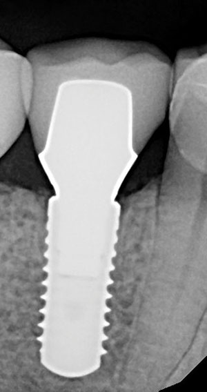
Conclusion
The finished implant crown can be seen from the facial view in Figure 13 and occlusal view in Figure 14. Figure 15 is the final radiograph with the implant crown cemented to place. I have found this process to be efficient and predictable using TAUB’s innovative products.
For additional information about TAUB products, call (800) 828-2634 or visit the website located at taubdental.com.


