In 2000, the Lava CAD/CAM system (3M ESPE) for crown and bridge restorations was clinically introduced in 3M ESPEís experimental operatories in Germany. The first university study began in 2001, with 5-year recall results being published in 2006.1
Five years ago in 2002, after receiving FDA approval, Lava was first introduced into the United States commercially and has become a widely used all-ceramic system.
Lava is a zirconium oxide-based crown coping and bridge framework system that provides for both underlying strength and aesthetics when veneered according to
recommended techniques with the appropriate oven-fired layering porcelains. It can serve as an anterior or posterior all-ceramic alternative to porcelain-fused-to-metal crowns and bridges in many, but not all circumstances.
This 2-part article discusses and presents solutions for the most commonly observed techno-clinical challenges as observed by experienced team members from 4 different Authorized Lava Milling Centers (ALMCs). ALMCs are responsible for the design and milling production of copings and frameworks. The ALMCs that participated in this endeavor were (in alphabetical order) Colonial Dental Studio in Davenport, Iowa; Dental Crafters in Marshfield, Wis; Issaquah Dental Lab in Issaquah, Wash; and New Image Dental Laboratory in Atlanta. The following question was posed as the premise for this article: “What can outsourcing dental laboratories and/or their doctors do to better assist you in providing them with the best possible milled copings and substructures?” The purpose of this question was to gain information that would be valuable in achieving better technical results, improving team relationships through mutual understanding, and optimizing patient outcomes for those receiving Lava restorations from their doctors.
Part 1 (Dentistry Today, October 2007) dealt with some of the most common challenges presented by dental laboratories that outsource the fabrication of Lava zirconium oxide copings and bridge frameworks to an ALMC. We noted that a variety of problems that are not caught and solved at either the doctor or outsourcing lab level must ultimately be addressed by the ALMC. Time and money could be saved if problems are identified and solved early in the process. Part 2 will continue a discussion of the challenges, as identified by the ALMCs, that lie within our responsibility as doctors prescribing and preparing cases for Lava restorations. ALMCs cite two major areas that deserve our attention to improve the quality and flow of work in and out of their facilities. The first one relates to model work that is done in the dental office and prepared for shipment directly to an ALMC. Specific preparation issues will be the second subject of discussion. (Although impression errors are an ongoing issue for outsourcing laboratories, most of these technical problems are dealt with before cases are sent to an ALMC, so they were not identified as a major doctor issue at the ALMC level. As a result, impression challenges will not be covered in this article.)
MODEL WORK CHALLENGES AND SOLUTIONS
If doctors do their own model and die work, sending it directly to an ALMC, then they must take responsibility for certain related challenges that may affect the quality and timeliness of the CAD/CAM work being requested (Figure 1). The type of stone used, the model base design, the quality of model pours, and any subsequent in-office die trimming are all sources of potential problems for the ALMC if one does not know exactly how to perform these tasks specific to a CAD/CAM zirconium oxide system. Also, as with the outsourcing labs previously discussed in Part 1, if the dental office team improperly packs models and dies for CAD, then the risk is much higher that they will arrive in a damaged condition.
All model work completed in the dental office should be done according to the Lava All-Ceramic System Laboratory Preparation technical guidelines bulletin (3M ESPE). Doctors and their dental office team must ensure that all model work is then properly packed for shipment. Before packing and sealing the case box, a trained team member should perform a careful inspection. Time should be taken to check that all model work has been performed properly and that the prescription is both legible and complete.
PREPARATION CHALLENGES AND SOLUTIONS
According to feedback from ALMCs, preparations are the main source of technical challenges they receive from their doctors. ALMCs report that they frequently observe a variety of preparation problems that can make it difficult to move the work through the scanning, design, and milling process efficiently. Problems range from knife-edge margins and J margins to undercuts and dimensional challenges. At the very least, preparation problems often require unnecessary phone calls to the doctor and/or the outsourcing laboratory. In some cases, because of the seriousness of some of these challenges, the quality of the case can be compromised, and returning the case for re-preparation may sometimes be the only option. Ironically, iatrogenic preparation errors, as seen in the laboratories and reported in this article, are almost always preventable or repairable at the initial operative stage prior to taking the final impression.
 |
 |
|
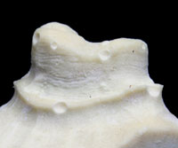
Figure 1. This die was sent in with numerous bubbles. The ALMC must pour a new model before scanning and design can begin. |
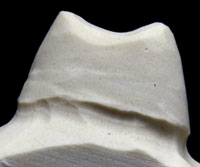
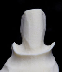
Figure 2. Note the knife-edge margin evident around the buccal aspect (right side) and lingual aspect of this otherwise nicely done preparation. |
 |
 |
|
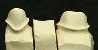
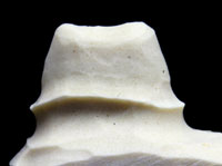
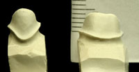
Figure 3. An example of beautifully prepared chamfer preparations. Well-defined, 0.7-mm to 1.0-mm (360?) chamfer margins are ideal for scanning and CAD. They will result in milled copings/frameworks with sufficient room for the layering porcelains, natural emergence profile, and optimal aesthetics in the cervical areas. |
Figure 4. A model cut with ideal chamfer margins can be a valuable visual aid. Whether creating a beautiful sculpture or an exceptional preparation, beginning with the final form in mind positively affects the final outcome. |
 |
 |
|
Figure 5. Note the undercut areas that are evident circumferentially on the die in the cervical one-third. This over-reduction was a result of utilizing a round bur to create a chamfer margin depth cut. It must be blocked-out with wax prior to scanning. |
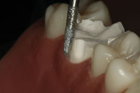
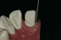
Figure 6. A chamfer of a predetermined depth is developed by carefully cutting the margin at one-half the tip width of the bur. Shown is an 856-018 chamfer bur that has a tip width of 1.45 mm and will create a 0.7 mm chamfer when used properly. |
Knife-edge margins are contraindicated for any type of all-ceramic restoration including aluminum oxide or zirconium oxide systems. (This style of margin is only appropriate for certain metal applications.) The knife-edge margin can be created unintentionally by using a bur that is too small in diameter to cut an adequate chamfer or when the preparation is prepared too conservatively (Figure 2). This can create problems in identifying and scanning the margin. It also tends to lend itself to exaggerated contours in the cervical one third, since there is not enough room for both the coping thickness and an adequate thickness of layering porcelain. The resulting bulkiness can lead to improper food deflection and possible periodontal problems down the road for the patient.
The chamfer is the ideal margin design for zirconium and aluminum oxide coping system restorations. When adequate tooth structure is available, the ideal minimal chamfer depth is 0.7 mm to 0.8 mm to allow room for the underlying coping and adequate layering porcelain (Figures 3 and 4). It is interesting to note that a well-executed chamfer seems to be a difficult design for many practitioners to master. This can be confirmed if one critically examines cases entering our dental laboratories. Some noted educators, having observed this as well, have recommended utilizing a modified shoulder design in lieu of a chamfer preparation. While a modified shoulder design will work for these porcelain systems, it is a less conservative margin design compared to a properly executed chamfer. Others have advocated utilizing a round bur technique to make a circumferential depth cut to establish a chamfer margin. This technique can lead to circumferential undercuts when not done carefully (Figure 5). Still others have advocated the use of gingival curettage diamonds, known as K-type diamonds (eg, 878K Axis Dental or Brasseler USA), probably with the intention of preventing the J margin. These burs have tips that are pointed instead of bullet-shaped like the 856 chamfer bur series. Unfortunately, when used in what have turned out to be the most popular sizes (014 and 016), these K-type burs create shallow chamfers in the range of 0.3 mm to 0.5 mm. Although less severe than in the case of a knife-edge margin, this can also lead to overcontouring issues and aesthetic problems, as referred to in Figure 2. However, it is important to note that when preparing small teeth such as mandibular anteriors or maxillary peg laterals, very shallow chamfers may be the only choice. In these cases, a K diamond might be a good bur to use, and our dental technicians must simply deal with the contour and aesthetic challenges that result as best they can.
When a tapered 856 bur is used to prepare a chamfer margin, the cut should be made to one-half the tip width of the bur. The depth of the chamfer margin thus becomes dependent on the size of the bur used (Figure 6). Manufacturers can supply the bur dimensions upon request, or burs can be accurately measured with digital calipers.
 |
 |
|
Figure 7. This is a dramatic example of a J margin created by overpreparation with a chamfer bur. Even if a CAD/CAM coping is designed here, there will be significant challenges for the ceramist and potential for margin damage of the die and solid model. (Also note the circumferential undercut in the cervical one-third and sharp line angles at the occlusal aspects.) Diplomatic technician-doctor feedback resulting in a prep revision is the best solution here. |
Figure 8. An end-cutting bur can be used to correct a J margin by removing the outer ìlipî quickly and without damage to the tissue or further reduction of the axial walls. (An M839 Axis Dental bur is shown here. This bur type is usually used to refine and smooth a shoulder for pressed ceramic preps.) |
A problem with the 856 bur design can occur if the tip is carried into the tooth too deeply, causing a J margin (Figure 7). Careful post-preparation and preimpression inspection with a sharp explorer and/or visible inspection with magnification can easily identify the problem before the case is sent to an outsourcing lab or ALMC. This can then be corrected by morphing the J margin into a modified shoulder preparation. This is done by carefully reducing the outer marginal edge adjacent to the gingival collar with a M839-014 or M839-016 (Axis Dental) end-cutting bur. (An equivalent bur from Premier, Brasseler USA, SS White, or another bur manufacturer may be used as well.) End-cutting burs are an ideal choice because they will not harm the gingival tissue as the prep correction is completed (Figure 8).
 |
|
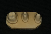
Figure 9. An axial wall height of 4 to 5 mm interproximally will ensure that there is adequate dimensional room to design and mill the 9-mm, 2-abutment pontic interconnectors required for this posterior bridge. |
A final preparation challenge cited by the ALMCs is related to the axial wall height of finished bridge abutment preparations. This problem occurs when there is inadequate room for framework dimensions in the interproximal areas. In designing strong tooth-to-pontic interconnectors, the dimensional requirements are minimal at the mesial and distal surfaces of the abutment teeth adjacent to the pontic. An important part of the solution to this problem is to know what dimensions are required in order to design a strong interconnector that properly supports the layering porcelain and resists the forces of mastication. As a rule of thumb, axial wall height of the prep, or prep and core, at the marginal ridge areas should be 4 to 5 mm minimum (Figure 9). Anterior interconnectors for zirconium oxide are ideally milled at 7 mm2, while posterior interconnectors are milled at 9 mm2. The Lava CAD system will not allow the mill to create a framework with less than ideal interconnector dimensions. To do other-wise could compromise the strength and/or aesthetics of the final prosthesis.
The doctor should complete a preoperative assessment of the available room in the occlusal-gingival and buccal (facial)-lingual dimension before preparation is begun. Ideal interconnector dimensions should be kept in mind. According to the ALMCs, the vertical height of the interconnector, between the abutment teeth and the pontic(s), is extremely critical to the strength of the beam as it is loaded under occlusal compression in function. In order to gain needed vertical interconnector room for a fixed bridge utilizing a zirconium oxide framework, the practitioner may want to consider placing the margin deeper cervically. However, while the option of placing the interproximal margin deeper to extend the usable axial wall height can be a potential solution, the proper biologic width must always be respected to ensure postoperative gingival health.
If tooth wear and a resulting decrease in available restorative vertical dimension is severe enough to obviate the achievement of proper interconnector dimensions with preparation and margin placement techniques alone, then the most conservative approach should still be considered before proceeding. Despite the added cost and time for the patient, an interdisciplinary approach and diagnosis may be the correct way to proceed.
For example, treatment options such as crown lengthening done by the periodontist can sometimes be a solution as a prerestorative procedure. In still other very select cases, opening the bite (OVD) may be the only vi-able alternative. Any decision to move in this direction, by the nature of the work it necessitates, will radically change and complicate the treatment plan.
CONCLUSION
Ultimately, excellent communication and direct responsiveness in enacting solutions for any identified team challenges will help to ensure success for CAD/CAM systems like Lava. The implementation of consistent teamwork among doctors, outsourcing labs, and ALMCs will yield optimal restorative results, reduce mutual stress, and maximize profits. Laboratory teams should encourage their doctors to fully understand the indications for zirconium oxide copings and frameworks, preparation requirements, and certain laboratory technical requirements. Most importantly, preparations should be designed with the scanning, CAD process, and end product in mind. Finally, an inspection for quality, completeness, and proper shipment preparation of all materials being sent into the ALMC, whether by an outsourcing laboratory or the doctorís office, will be time well spent.
Additional Resources/Reading
Shillingburg HT Jr, Jacobi R, Brackett SE. Fundamentals of Tooth Preparations for Cast Metal and Porcelain Restorations. Hanover Park, IL: Quintessence Publishing; 1987.
3M ESPE. Lava All-Ceramic System Laboratory Preparation. St Paul, MN: 3M ESPE; 2002. http://solutions.3m.com/wps/portal/3M/en_US/3M-ESPE/dental-professionals/products/category/lab-digital/lava-crowns-bridges. Accessed September 24, 2007.
Note: This technical guide regarding LAVA requirements is available for dental laboratories and is also applicable for doctors who prefer doing their own model and die work. The instructions should be reviewed thoroughly and followed exactly to help prevent technical problems or production delays in the milling centers.
Reference
1. Nothdurft FP, Rountree PR, Pospiech PR. Clinical long-term behavior of Zirconia-based bridges (LAVA): five years results. Presented at: IADR Pan European Federation; September 13-16, 2006; Dublin, Ireland. Abstract 312. http://iadr.confex.com/iadr/pef06/techprogram/abstract_85451.htm. Accessed September 24, 2007.
Acknowledgment
The author extends his heartfelt thanks to all the experienced personnel from the Authorized Lava Milling Centers who participated in this project by providing candid information, technical advice, and photos needed to write this article.
Dr. Adams, a graduate of the University of Michigan, is an assistant clinical professor in the Dental Residency Program at the University of Toledo College of Medicine. He lectures internationally emphasizing doctor-technician relationships and techno-clinical perspectives. He also facilitates hands-on preparation workshops designed to optimize the utilization of all-ceramic systems. In addition to his years in private practice, he has had the opportunity to serve as a doctor-technician liaison for many dental laboratories throughout North America for more than 12 years. Dr. Adams is a Contributing Editor for Dentistry Today and is listed in Dentistry Today’s Top Clinicians in Continuing Education (2004 to 2007). In addition, he also serves on the Advisory Board for Spectrum Dialogue (Palmeri Publications). Dr. Adams is a member of the ADA, AGD, AACD, and the National Association of Dental Laboratories. For Dr. Adams’ contact and course information, visit adamsdentalseminars.com.
Disclosure: Dr. Adams has no financial interest in any of the companies referred to in this article.