Restorative dentists have an essential role in the diagnosis of the restorative needs of patients treated with dental implants.1 An implant template is the means of communication used to transfer positioning requirements to the surgeon, who can then place the implants in positions that allow for ideal restoration of the occlusion.2 Templates are necessary even for single implants.3
According to Misch, the surgical template dictates to the surgeon the implant placement that offers the best combination of (1) support for the repetitive forces of occlusion, (2) aesthetics, and (3) hygienic requirements.4 A well-designed template can reduce surgical time, improve the accuracy of implant placement, reduce the need for expensive, vector-changing abutments, and improve the aesthetic emergence profile of the restoration.
There are a variety of template types, ranging in sophistication and cost from inexpensive vacuum-form shells to computerized tomography (CT)/computer-derived templates. The following types of implant templates have been used:
Restorative implant templates indicate the shape and position of the proposed restoration(s) but do not dictate the osteotomy path for the surgeon. These are generated from diagnostic models and generally include (1) vacuum-form duplicates of diagnostic models, (2) acrylic resin material based on a diagnostic wax-up, or (3) direct resin adaptation to the diagnostic model. Each of these templates cover the occlusal tables of adjacent teeth for support. The proposed implant site is often represented in acrylic on the restorative template by the facial surface of the desired restoration or by the intact acrylic representation of the entire proposed restoration for the surgeon to manipulate as is appropriate.
The advantages of restorative templates are their ease of fabrication, commonly available materials and techniques, and low cost. The disadvantage of the restorative template is that it does not dictate the position of the osteotomy.
Surgical implant templates may also indicate the shape of the proposed final restoration but dictate the osteotomy as well. They are generally based on CT scan data and computer-driven design and fabrication. In this category, a CT scan is taken of the patient’s jaw. The implant surgery is planned using CT scan, and a computer-assisted process relates the proposed axial and depth alignment. Surgical CT-based templates are generally fabricated by 1 of 2 processes: (1) CAD/CAM (Computer-Assisted-Design-Computer-Assisted Manufacture) milling, and (2) stereo-lithography.
The advantages of using surgical templates include predictability of placing implants in proper alignment, avoiding injury of adjacent structures (teeth, sinuses, or cortical plates), and reduced surgical time,5 with corresponding improvement in postoperative healing. The disadvantages of using surgical templates are the higher start-up costs of computer software and the learning curve associated with reading CT scans and creating the correct treatment plan. Furthermore, dentists might hesitate to utilize surgical templates because of the added expense and inconvenience to the patient, especially for less involved cases.
Therefore, restorative templates are quite simple, while surgical templates are more complex. The effort the restorative dentist invests in designing and fabricating an implant template, and the type of template selected, should reflect information that should be transferred to the implant surgeon to assure a successful prosthetic outcome.
For implant treatment consisting of one to a few implants, dentists may be able to communicate the necessary information adequately with the simpler restorative template. Nevertheless, relatively simple cases can have only a small margin of error. Each implant and restoration has a set of challenges determined by location, hard- and soft-tissue anatomy, spacing between adjacent teeth, and other aspects of local anatomy involving location of neurovascular bundles, sinuses, and cortical plates of bone. Predetermining the appropriate osteotomy path for the surgeon could greatly assist the surgical procedure.
A type of template that is seldom used but has advantages of both the restorative and surgical templates is the surgical guide-tube template. It is fabricated as a restorative template with a hard resin material that rests on the occlusal table of adjacent teeth. As opposed to relying on a CT scan, the restorative and surgical considerations are related by bone mapping and radiographic verification.
This article will present a technique for fabricating guide-tube templates, including verification of accuracy and guidelines for use during implant surgery.
MATERIALS AND METHODS
 |
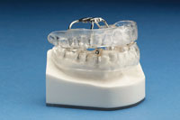
| Figure 1. Surgical guide-tubes (Stent Guide Tubes, 3i Implant Innovations Corp). |
Guide-tubes are prefabricated, stainless steel, radiopaque tubes that can be obtained from implant manufacturers (eg, Stent Guide Tubes, 3i Implant Innovations, Figure 1). They are manufactured with only a single internal diameter of approximately 2.3 mm, which accommodates only the initial size osteotomy burs, and a length of 10 mm that can be trimmed to fit the thickness of the template or to accommodate the vertical space necessary for the surgical handpiece. The guide-tubes are embedded into acrylic models via laboratory acrylic processing or by a direct acrylic process on models.
Implant surgery begins with the creation of a small diameter osteotomy. Guide-tubes will dictate the path of these initial burs. After the initial osteotomy is prepared, the template is removed from the mouth and subsequent larger diameter burs tend to follow the path initially created. To relate the access tube properly in the buccal-palatal/lingual dimension of bone, one additional diagnostic step (bone mapping) is necessary to predetermine the outer dimensions of the cortical plates of the implant site.
When evaluating the patient clinically, the buccal-palatal/lingual dimension of the edentulous site is sounded or bone-mapped to determine the depth of the soft tissue covering bone at the implant site.6,7 Several drops of anesthetic are placed, a periodontal probe is inserted horizontally through the soft tissue to the bone, and the depth is recorded for transfer to the diagnostic models. This is repeated in 3-mm vertical steps on both sides of the edentulous space, moving apically so that the approximate buccal-palatal/lingual dimensions are determined. This helps to create a safer osteotomy by allowing the osteotomy to be aligned within the cortices, thereby avoiding penetration of the cortical plates. If there is a substantial amount of bone in this direction, the decision regarding where to place the guide-tube in the buccal-palatal/lingual plane will be based on the requirements of the final restoration (type of retention, aesthetic needs, and diameter of the implant). If there is not a substantial amount of bone in this direction, the only option will be to center the guide-tube in the middle of the bone. The mesial-distal position and axial angulation are later verified after the template is processed.
The fabrication process is similar for a device to be used with a single implant or multiple implants. For descriptive purposes, a template based on replacement of a single tooth, with teeth on each side, will be described.
 |
 |
| Figure 2. Guide-tube placed into the center of the edentulous space. | Figure 3. Centered guide-tube, occlusal view. |
 |
 |
| Figure 4. Surgical guide-tube template on the diagnostic model. | Figure 5. Template in place intraorally at the time of radiographic verification. |
In the laboratory, a guide-tube is placed onto the model with the center of the tube in the ideal position for the specific needs of the proposed restoration and within the buccal-palatal/lingual axial limitations of the bone as determined by bone mapping (Figures 2 and 3). At this point, the template is processed using resin with the guide-tube in place (Figures 4 and 5). For short span templates where only 1 or 2 implants will be placed with adjacent teeth existing on both sides, a visible light-cured material (Triad TranSheet Material, DENTSPLY/Trubyte) with the model coated to allow release of the template can be used for direct, in-office fabrication. For longer edentulous spans, a stronger laboratory processed dense acrylic template should be made. For either the direct in-office technique or the laboratory processed technique the template should be made thick enough to prevent distortion or fracture.
 |
 |
| Figure 6. Radiographic verification indicating the guide-tube is properly positioned. | Figure 7. Ideal implant placement of 4.0 x 13-mm 3i Osseotite Certain NT implant (3i Implant Innovations). |
Verification of the correct mesial-distal angulation of the guide-tube within the template is accomplished radiographically (Figure 6). The template is placed onto the teeth and a bitewing radiograph is taken. A pencil line is drawn on the developed film through the center of the guide-tube and extended apically through the projected osteotomy path. The pencil line should be centered between adjacent clinical crowns, and as the line extends apically, the adjacent roots should not be contacted. The desired depth of the implant along the pencil line should not violate the local anatomy, including neurovascular bundles or sinuses, and should be short of those anatomical structures by a distance mutually agreed upon by the restorative dentist and surgeon (Figures 6 and 7).
 |
 |
| Figure 8. The osteotomy pathway projected through this guide-tube is poorly centered between adjacent roots. | Figure 9. The corrected guide-tube position indicating the appropriate osteotomy pathway. |
 |
 |
| Figure 10. A Gelb Radiographic guide pin in place indicating an appropriate initial osteotomy. | Figure 11. A properly positioned 4.0 x 13-mm 3i Osseotite external hex implant (3i Implant Innovations Corp). |
If the guide-tube does not project a safe osteotomy path, it can be modified in the same clinical visit (Figures 8 through 11). A hemostat is used to grip the tube portion that extends out of the template, and the tube is removed and placed aside. The hole that remains in the template is broadened to accommodate the axial correction of the guide-tube in the mesial-distal plane only. The guide-tube is placed into the now-corrected position, luted with acrylic or flowable composite, and then cured. The template is again placed onto the teeth, and another radiograph is exposed to verify that the guide-tube is correctly positioned.
The template with the corrected guide-tube is now complete. The buccal-palatal/lingual position was determined by bone mapping, and the mesial-distal position was determined radiographically. The verified template, the radiograph, and the bone-mapping data are sent to the surgeon.
Once the basic surgical guide-tube template methodology described above is mastered by the clinician, helpful variations can be introduced.
 |
 |
| Figure 12. A second provisional restoration template seated on articulated models. The shape of the previously unprepared teeth was preserved in this template and assisted in the positioning of the guide-tube. | Figure 13. An occlusal view of the pontic site with space to accommodate the guide-tube. |
 |
 |
| Figure 14. The guide-tube in place with a 2.0-mm diameter surgical twist bur in position, demonstrating how it is extended through the surgical guide-tube template during surgery. | Figure 15. Radiographic verification of the guide-tube indicates an improper osteotomy pathway. |
 |
 |
| Figure 16. The second radiograph of the corrected guide-tube position indicates the correct osteotomy path. | Figure 17. A well-positioned 3.25 x 15-mm Osseotite implant (3i Implant Innovations) in a site limited by the curvature of the canine root and the mesial root projection of tooth No. 13. |
In a situation where a failed bridge must be removed, the restorative dentist can fabricate both a provisional restoration and a surgical template at the same clinical visit if implants are included in the treatment plan. In this situation (Figures 12 through 17), a preoperative impression of the area of the failed bridge is taken using a bite tray (Triple-Tray, Premier Dental Products) with a polyether impression material (Impregum, 3M ESPE AG). After bridge removal, caries control, and preparation of the abutment teeth, a bis-acrylic provisional material (Protemp 3 Garant, 3M ESPE AG) is injected into this impression and then seated on the prepared teeth. Following conventional techniques for fabricating and finishing the first provisional bridge, a second provisional bridge is fabricated and properly adjusted. Before the patient is dismissed, the edentulous site is bone-mapped. Alginate impressions of the prepared teeth, the opposing arch, and a bite registration are made. The first provisional bridge is cemented, and the patient is dismissed. The second provisional will fit the articulated models.
This second provisional bridge can be converted to a surgical guide-tube template. This approach offers significant benefits. First, in contrast to when natural teeth are present, once a bridge is removed, the abutment teeth provide little reference relating to the local anatomy. However, if the shape of the previous bridge is preserved in the second provisional restoration—and if that restoration is well-seated on the articulated models—the radiographs can assist the dentist in positioning the guide-tube(s).
In Figures 12 through 17, note the limiting local anatomy in the tooth No. 12 implant surgery site, where the apical third of the canine root vectors sharply to the distal and there is a mesial root projection associated with tooth No. 13. Preoperatively positioning and verifying the guide-tube in this template facilitated safe and predictable implant placement and restoration. Furthermore, the provisional surgical template technique utilizes the tooth morphology (the pontics of the failed bridge) and may allow the clinician to bypass the dental laboratory for diagnostic template fabrication. This will facilitate prompt scheduling of the patient for implant surgery.
Although the surgical guide-tube template is relatively easy to fabricate, accuracy during all phases of fabrication is essential. Any compromise in the accuracy of the measurements or fabrication will increase the likelihood of error or abandonment of the template at the time of surgery. Therefore, a review of potential problems and how these can be prevented is helpful.
POTENTIAL PROBLEMS
The template must accurately fit so it can be placed on the teeth in a reproducible manner. It should be stable and retentive, even when not held in place. A radiograph of the template should be taken and bone mapping accomplished as previously described. Furthermore, the device should be polished to avoid rough surfaces that are difficult to disinfect or sterilize.
Communication between the restorative dentist and surgeon is essential. After fabrication of the template, it should be determined in advance how to disinfect or sterilize the template. The heat of an autoclave would deform the acrylic. Patients should never manipulate the template or have the template in their mouth unless under supervision. This reduces the likelihood of them inadvertently deforming the template.
 |
| Figure 18. An initial 2.0-mm diameter implant bur attached to a latch-head handpiece resting in a guide-tube template on the model. The necessary vertical space is illustrated. |
Other suggestions pertain to the surgical procedure. The guide-tube template can add significant vertical length to what is required by the surgical handpiece and burs (Figure 18). The surgeon should be informed of this well in advance of the surgery so that appropriate-length burs are available. The template itself can be reduced from the occlusal surface to reduce the interarch dimension, thereby accommodating both the handpiece and bur.
The template, even when fabricated with a rigid acrylic base, can move off the occlusal table if the surgeon encounters dense bone. When this occurs, the osteotomy bur deflects against the inner wall of the guide-tube. The lever-arm force generated by the relatively long handpiece causes the entire template to be lifted off the teeth, even though the surgeon may feel that the template is firmly in place. The same problem can be encountered when preparing a tooth socket during immediate implant placement or even after an extraction site has healed. The dense lamina dura of the socket wall can easily reroute the bur, creating a torquing force against the inner walls of the guide-tube, lifting the template out of place.
This problem can be prevented. The surgeon should first create a partial-length osteotomy that is short of the ideal length. Before exposing a radiograph with the guide pin in place, the bur should be removed from the handpiece and reseated through the template into the osteotomy preparation. This will allow verification of passive placement through the guide-tube without displacement of the template. The reason for detaching the bur from the handpiece is to remove the lever-arm effect of the handpiece.
If the template lifts up during drilling or if at verification the bur does not seat passively through the guide-tube, modification of the initial osteotomy toward the correct path is needed. This should be performed without the template in place. Since osteotomy burs are generally end-cutting instruments, a side-cutting correction bur should be used (eg, the Lindemann Bur, Salvin Corp).
 |
 |
| Figure 19. A denture style surgical guide-tube template. | Figure 20. The denture style surgical guide-tube template facilitated the proper positioning of these 3i Osseotite external hex implants. View during surgery, before removal of the surgical mounts. |
Another use of guide-tubes is demonstrated in Figures 19 and 20. A CT scan indicated abundant buccal-palatal bone for implant placement for a treatment plan consisting of an acrylic/noble metal, screwed-down, fixed hybrid full arch prosthesis. The implants were to be placed on half arch at a time to allow the remaining teeth to strategically support the existing prosthesis. A denture tooth setup was fabricated and approved by the patient. The setup was duplicated in clear acrylic in a denture duplicating flask (Lang Denture Duplicator, Lang Dental Mfg Co) and re-mounted on the articulator. A surgical guide-tube template was created. Guide-tubes were positioned for implants that are suitable for the anatomy and future prosthesis. Figure 19 shows the surgical template after the guide-tubes were luted with flowable composite and before polishing. Figure 20 shows the properly positioned implants just prior to removal of the blue colored “surgical mounts.” This particular brand of implants is packaged with these devices attached to the implant. The surgical mounts enable the sterile transfer of the implants from the package to the osteotomy sites. The surgical mounts were subsequently removed. The healing (cover) screws were placed and the site was sutured closed for a 4 month healing period (#I Osseotite External Hex implants, 3i Implant Innovations Corp).
DISCUSSION
A surgical guide-tube template allows the implant team to plan preoperatively for proper positioning of implants and represents a prescription for the projected osteotomy to avoid damage to adjacent roots or compromise of important anatomic structures.
There is a learning curve with this technique which will be reduced if the restorative dentist and implant surgeon discuss the fabrication process, discuss how to avoid potential errors, and if they understand their respective challenges in bringing the case to a satisfactory prosthetic conclusion, since they both contribute to the successful outcome.8
This author considers the surgical guide-tube template to be a more informative communication tool than a restorative template, but it is important to emphasize that it is not appropriate for all cases. The use of the surgical guide-tube template should be limited to clinical situations where the majority of the implant dimension can be predetermined through bone mapping and radiographic verification. For cases where the entire surgical path must be preoperatively verified, a CT scan surgical template is generally needed.
The expense and time the restorative dentist chooses to invest in designing and fabricating implant templates, and the type of template selected, should be a reflection of the amount and type of information needed to be transferred to the implant surgeon to assure a successful prosthetic outcome.
There is no single template technique that fulfills all the needs of the implant team. Simple restorative templates and surgical templates all have their place in the modern dental practice. CT scan-derived templates are very useful but are also technique sensitive, and clinical application requires a substantial learning curve. The benefits of surgical guide-tube templates are their low cost, readily available materials, minimal time for fabrication, and reduced radiation exposure.
CONCLUSION
This article has described the fabrication and clinical use of the surgical guide-tube template.
The use of templates is associated with greater precision in implant rehabilitation. A simple referral to the implant surgeon without advanced planning and involvement of the restorative dentist can greatly reduce the effectiveness of implant therapy.
Acknowledgment
The author would like to thank Mr. Wayne Szara of 3i Implant Innovations for his dedicated effort in diligently and accurately responding to implant inquiries. He can be reached at (800) 342-5454. And William “Coach” Bartosiak of North American Dental Laboratory is responsible for all restorations placed by the author and is a wellspring of knowledge in implant dentistry. He can be reached at his office at (847) 982-9788.
References
1. Solow, RA. Simplified radiographic-surgical template for placement of multiple, parallel implants. J Prosthet Dent. 2001;85:26-29.
2. El Askary, Abd El Salam. Reconstructive Aesthetic Implant Surgery. Ames, Iowa: Blackwell Munksgaard; 2003:2:33-34.
3. Cranin AN. Root form implant prosthodontics: Single tooth implant restorations. In: Cranin AN, Klein M, Simons M, Simons A, eds. Atlas of Oral Implantology., 2nd ed. St. Louis, MO: CV Mosby; 1999:58-67.
4. Misch, CE, Dietsch-Misch, F.; Diagnostic casts, preimplant prosthodontics and surgical templates. In: Misch, CE.: Contemporary Implant Dentistry., 2nd ed. St. Louis, MO: CV Mosby; 1999:58-67.
5. Benjamin, LS. The evolution of multiplanar diagnostic imaging: predictable transfer of preoperative analysis to the surgical site. J Oral Implantol., 2002;Vol. 285( No.3):135-144., 2002
6. Flanagan DF. A method for estimating preoperative bone volume for implant surgery. J Oral Implantol. 2000;26:262-266.
7. Wilson DEJ. Ridge mapping for determination of alveolar ridge width,. Int J Oral Maxillofac Implants. 1989;4:41-43, 1989.
8. Small, BW. Surgical templates for function and esthetics in dental implants. Gen Dent., 2001 Jan-Feb;49(1):30-32,34.
Dr. Montrose has been practicing implant rehabilitation in suburban Chicago, Illinois, for 17 years. He attented the American Academy of Implant Dentistry Maxi-Course at NYU and will be receiving the fellowship award from the Academy of General Dentistry in July 2004 at the annual meeting in Anaheim, California. In addition to his private practice, he consults for surgical and restorative practices on implant diagnostics and treatment planning. He can be reached at his office in Lincolnwood, Ill, at (847) 675-6767 or at jmontr@comcast.net.