Together, the authors explore the Endodontic-Endo-Restorative-Prosthodontic (EERP) continuum. This 2-part article will focus on the pervasive endodontic problems vexing patients, restorative dentist, and endodontists. The authors provide alternative models and thought processes to treat the tooth in a nontraditional approach—from cusp tip to apex. In addition, they will propose immediate tools to implement these important changes.
|
|
||
|
INTRODUCTION
During patient treatment, the clinician needs to consider a multitude of factors that will affect the ultimate outcome. In simple terms, these factors can be grouped into 3 categories: operator needs, restoration needs, and tooth needs. The operator needs being conditions the clinician needs to treat the tooth. The restoration needs being the prep dimensions and tooth conditions for optimal strength and longevity. The tooth needs being the biologic and structural limitations for a treated tooth to remain predictably functional. In this article, we want to discuss failures of endodontically treated teeth that occur not because of chronic or acute apical lesions, but because of structural compromises to the teeth that ultimately render the tooth useless. We want to coronally shift the focus to the cervical area of the tooth and create awareness for an endo-restorative interface. To this end, we will introduce a set of criteria that will guide the clinician in treatment decisions to maintain optimal functionality of the tooth, as well as help in deciding when the treatment prognosis is poor, and when alternatives should be considered.
ENDODONTIC ACCESS
Endodontic accesses are traditionally conservative to the occlusal/incisal tooth structure. However, with the changes that have occurred in restorative dentistry, this technique is unnecessarily restrictive for the operator. In addition, it can be damaging to the more critical cervical area of the tooth.
To introduce the problem, we will present a case (Case 1 shown in Figures 1 to 4) that we feel is quite representative of a large percentage of endodontic accesses performed by general dentists and endodontists. This tragic story is replayed thousands of times each day in the United States and Canada.
CASE 1
 |
 |
|
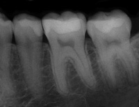
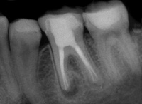
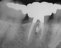
Figure 1. Case 1 (Figures 1 to 4): Preoperative view of tooth No. 19 in a 20-year-old female. |
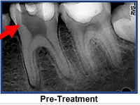
Figure 2a. Depicts the de-roofing problem discussed later in the article. The likely bur used by the referring general dentist was a 56-carbide. Red arrow delineates the typical gouging. |
 |
 |
|
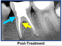
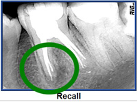
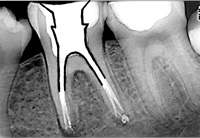
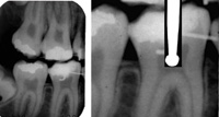
Figure 2b. Postoperative view provided by the endodontist. Blue arrow indicates the grossly excessive dentin removal of pericervical dentin. This serious gouging is typical of round bur access. Yellow arrow marks the large canal flaring with unacceptable dentin removal (blind funneling). Figure 2c. Shows incomplete healing of mesial root (green circle) at recall in spite of excellent “apical endodontics.” |
 |
 |
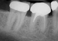
| Figure 3. Eighteen-month follow-up. In spite of generous access and aggressive canal enlargement, the lesion on the mesial root continues to enlarge. |
Figure 4. A more appropriate access shape is overlayed. Partial deroofing and maintenance of a robust amount of PCD is demonstrated. A soffit is depicted which includes pulp horns on mesial and distal. |
In Figure 1, we see a lower first molar of a 20-year-old female. These “young” teeth are dangerously hollow to begin with. By the time that 2 dentists with good intentions had finished working on the tooth, the molar was nearly worthless. The most important structures were so badly compromised that the tooth was permanently crippled.
| Table 1. The Hierarchy of Tooth Needs for Posterior Teeth | |||||||||
|
The general dentist created the first access using square ended fissure burs, (possibly one of the most iatrogenic instruments in the history of modern medicine and still the most popular bur in total sales1) and with the type of dentin removal that is the standard today (Figure 2a). The tooth was then reaccessed by an internationally recognized endodontist (Figures 2b and 2c). This model for generous removal of pericervical dentin (PCD) is common in many specialty practices.
Eighteen months later, the lesion on the mesial root continues to enlarge (Figure 3). In Dr. Clark’s restorative practice and Dr. Khademi’s endodontic practice, such a tooth does not warrant endodontic retreatment. The wholesale loss of PCD has reduced the value of this tooth to the point that when the tooth becomes symptomatic, extraction and replacement with an implant is a better option.
In fairness to our patients, we must either change the process, or make implants a first option instead of the eventual option. The new model of endodontic access is superimposed over the tooth in Figure 4.
A NEW MODEL FOR ENDODONTIC ACCESS
As we deconstruct endodontic access, it is crucial to understand the 5 catalyst forces that will change the future of endodontic access and coronal shaping. They are the following: (1) implant success rates (the bar is raised); (2) operating microscopes and microendodontics; (3) biomimetic dentistry; (4) minimally invasive (MI) dentistry; and (5) aesthetic demands of patients.
In both of our practices, our endodontic goals and armamentarium have been in a constant state of flux for nearly a decade as we have collaborated to bring the EERP continuum to maturity. The goal? To satisfy the demands of the above mentioned “Big 5” forces for change. In so doing we have come to realize that, when preparing endodontic accesses, our previous needs as dentists were often in conflict with the needs of the tooth.
|
Table 2. Glossary of Terms for Modern Endodontic Access and Acronyms |
|||||||||||||||||||||||||||||||||||||||||||
|
Table 1 represents the hierarchy of needs to maintain optimal strength and fracture resistance, along with several other characteristics needed for long-term full function of the endodontically treated tooth.
The brevity of this article precludes a full definition for all of the terms of the glossary (Table 2). However, there are 2 terms explained below. Others will be mentioned in the context of the feature cases.
Three-Dimensional Ferrule
The 3-dimensional (3-D) ferrule is the backbone of prosthetic dentistry. It has historically been described as axial wall dentin covered by the axial wall of the crown (or bridge abutment restoration). The research varies on the actual minimal vertical amount required, but the range of absolute minimums is from 1.5 to 2.5 mm.2-17 The clinician must remember that build-up material, although necessary, does not “count” toward the ferrule. A more comprehensive view of ferrule is needed, and is embodied in the term 3-D ferrule. There are 3 components of the new ferrule, first is the vertical component, which is described above. The second component is dentin girth (thickness). The absolute minimum thickness is 1.0 mm; however 2.0 mm is obviously a safer number. The third component is total occlusal convergence (TOC), or net taper. That is the total draw of the 2 opposing axial walls of the prepared tooth to receive a fixed crown. A net taper or TOC of 10° requires 3.0 mm of vertical ferrule; a TOC of 20° requires 4.0 mm of vertical ferrule.18-32 Deep chamfer marginal zones common with today’s porcelain crowns typically have a net taper of 50° or more, and therefore many of today’s aesthetic margins lose a millimeter or more of there original potential 3-D ferrule at the crown margin interface.
PERI-CERVICAL DENTIN
PCD is the dentin near the alveolar crest. While the apex of the root can be amputated, and the coronal third of the clinical crown removed and replaced prosthetically, the dentin near the alveolar crest is irreplaceable. This critical zone, roughly 4 mm above the crestal bone and extending 4 mm apical to crestal bone, is sacred for 3 reasons: (1) ferrule, (2) fracturing, and (3) dentin tubule orifice proximity from inside to out. The research is unequivocal; long-term retention of the tooth and resistance to fracturing are directly related to the amount of residual tooth structure.2,33 The more dentin we keep, the longer we keep the tooth.
SACRIFICE VERSUS COMPROMISE
 |
|
Figure 5. Radiographically ugly but clinically successful (20-year) endodontic treatment. This case was very likely done on a vital tooth. Residual PCD has buttressed this tooth to avoid fracture. |
In Case 1, significant dentin was sacrificed to facilitate expedient and safe instrumentation, and yet the endodontic treatment was failing. Contrast that case with the tooth seen in Figure 5. There was a significant compromise 20 years ago, when the dentist stopped removing dentin because the complete canal system could not be located and less than half of the distal root was filled. Despite this shortcoming, the “poor endodontic result” was successful, and the well-preserved PCD has buttressed the tooth making the overall case a smashing 20-year success.
LOOK, GROOM, AND FOLLOW: SHAPING VERSES MACHINING
A Mini-Interview/Dialogue With the Authors
Why are Gates Glidden burs so problematic?
 |
|
Figure 6. Extensive coronal flaring results in extrusion of obturation material in the furcation. The furcal strip perforation is a perfect example of the dangers of “Blind Funneling” with Gates Glidden burs. |
Dr. Clark: I abandoned Gates Glidden (GG) burs 12 years ago. I will explain why. Since the introduction of rotary files, GG burs have been used more aggressively and with more reliance on larger sizes (4, 5, and 6) to reduce binding and fracture of rotary files. GG burs have always been considered “safe” because they do not end cut and are self-centering. There is a significant problem here, which is “cervical self-centering.” Because the shank of the GG is so thin, it is difficult to “steer” the GG bur away from high-risk anatomy. As the GG bur straightens the coronal, or “high-curve,” it can shortcut across a fluting or furcation, and weaken and/or create strip perforations (Figure 6).
Why are round burs so destructive?
 |
 |
|
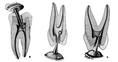
Figure 7. Text after text shows the same round bur technique relying on tactile feedback as the round bur drops into the chamber. |
Figure 8. If the pulp chamber is sufficiently large enough, then a round bur can truly “drop in” to the pulp chamber as shown here with a No. 6 round bur superimposed on the lower molar of this 11-year-old child. |
 |
|
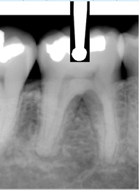
Figure 9. This case is much more representative of the spectrum of cases typically presenting for endodontic treatment. |
Dr. Khademi: The traditional way of initiating endodontic access is predicated on mental models that do not represent the day-to-day clinical reality presented to the clinician. Text after text shows the same round bur technique relying on tactile feedback as the round bur drops into the pulp chamber (Figure 7). These kinds of images, so frequently shown in dental school, textbooks and lectures are predicated on mental models based on occlusal decay in children.
If the pulp chamber is sufficiently large enough, then a round bur can truly “drop in” to the pulp chamber as shown here with a No. 6 round bur superimposed on the lower molar of this 11-year-old child (Figure 8).
The reality of day-to-day clinical practice is quite far removed from this, and these deeply ingrained mental models are a setup for occult iatrogenic trauma. More realistically, the case shown in Figure 9 is much more representative of the spectrum of cases typically presenting for endodontic treatment. Clearly, trying to drop a round bur into the scant or nonexistent chamber is not going to lead to the desired outcome even for a skilled clinician.
Instead, the size of the burs relative to the chambers, the omnidirectional cutting blades (which side cut very aggressively), and chatter common with this bur design are much more likely to lead to the kinds of outcomes seen in Case 1 (refer again to Figures 2a to 3).
 |
|
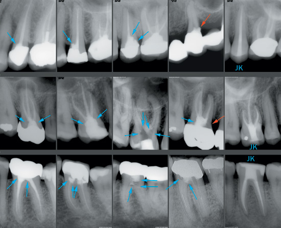
Figure 10. (Mural is described in the text.) Note: Blue arrows indicate gouges. Red arrows indicate perforations. “JK” indicates that case was done by Dr. John Khademi with adherence to the modern model of directed dentin conservation. |
So while round burs are destructive because they contribute to, or exacerbate, these problems; it is really the tactile based mental models predicated on these kinds of drawings showing round burs dropping into the pulp are the ultimate problem. Care and magnification can compensate, but only to a degree (Figure 10).
Figure 10: First Row
Note: Blue arrows indicate gouges. Red arrows indicate perforations. “JK” indicates that case was done by Dr. John Khademi with adherence to the modern model of directed dentin conservation.
Upper Bicuspids are deceptively difficult. At the peri-cervical level, they can be half as wide mesiodistally as buccolingually. This is further complicated by frequent invaginations midroot where round bur access is typically placed. This sequence shows the typical occult gouging in the first case and the misangulation and gouging as the sequence progresses ending in a perforation of a bridge abutment. The correct mesiodistal access of this tooth should be no wider than the coronal canal shape. The access may slightly converge from a broad buccolingually pulp chamber as it moves towards the occlusal in the buccolingually dimension. Round burs simply cannot create this kind of shape.
Second and Third Rows: Molars
I was overwhelmed with the sheer number of gouged up molar cases while mining my The Digital Office image database. Essentially all previously accessed molars were gouged to some degree. The first upper and lower molar cases show what many might consider acceptable access extension and were obviously cut with round burs. Both are gouged. The third upper and lower cases both have frighteningly thin pulpal floors with blushing dentin. The upper fourth case is deceptive in that it is perforated, while the worse looking lower case is not, but the pulpal floor is paper-thin. The last upper molar case (which has a Class V resorption repair) shows what is possible with practice, microscope level magnification, an assistant’s side and the right instruments. The lower molar shows the type of access that should be routinely achievable with high-powered loupes and the right instruments.
Why is complete de-roofing so dangerous?
Dr. Clark: When Dr. Khademi first mentioned maintaining a “soffit,” which is a little bit of roof around the entire coronal portion of the pulp chamber, I was perplexed at first. Today, it makes perfect sense because cleanup is easier, and I feel a great sense of pride in this important advance in MI access. Research will certainly need to be done to validate the strength attributes of the roof strut, or soffit. However, in the absence of a compelling reason to remove dentin, our default position should always be the conservative one. This 360° soffit, or roof-wall interface, can also be compared to the metal ring that stabilizes a wooden barrel.
Dr. Khademi: Presuming one could drop into the pulp chamber in the way drawn and described above, the chamber roof would now be removed by scooping it up and away with a round carbide. A 2-dimensional (2-D) drawing, with the relatively small size of the bur and chamber roof overhanging a large pulp chamber, makes this seem like a reasonable proposition. The chamber walls are somehow always drawn flat even though they are cut by a round bur.
In reality, it is truly impossible to do: to cut flat walls in 3-D with a round instrument. What happens is that the chamber is unroofed in some areas leaving pulpal and necrotic debris, and the walls are overextended and gouged in other areas. Furthermore, the internal radius of curvature at many of the pulpal line angles is simply too small for all but the smallest of round burs.
 |
|
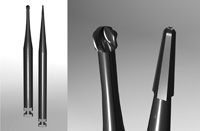
Figure 11. Illustration comparing the CK endo access bur to the corresponding round bur. |
In the final analysis, round burs point cut in an endodontic access application, when instead what is needed is planing. What is needed is a new set of mental models based on vision, and a new set of instruments reflective of the task at hand and the desired shaping outcomes. The new vision based mental model is look, groom, follow. The new burs are all rounded-ended tapers (Figure 11). It is an illustration comparing the CK Endodontic Access bur to the corresponding round bur. The tip size of these burs is less than half as wide as the corresponding round bur. One of the prototype CK Endodontic Access burs has had (right) is shown and contrasted with the corresponding surgical length round bur (left). These burs, designed by Drs. Clark and Khademi, will be available from SS White Burs.)
CASE 2
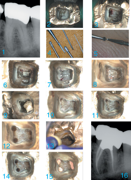
This case (Figure 12) shows a completely different vision-based model (look, groom, follow) for creating access to the root canal system. This model is predicated on a reversal of many traditional access concepts, which required the elimination of some instruments considered integral to endodontic access and the consequent development of new instruments and techniques.
 |
|
Figure 12. Mural is described in the text. |
First, restorative materials are sacrificed so that PCD is not compromised. A wide swath is cut through the occlusal surface of the restoration just to the level that dentin is encountered. This generous access allows the clinician to more accurately read the color map looking for clues leading to the initial locations of the pulp tissue remnants (PTR), or where the PTR were in a necrotic system (PTR space).
Second, the clinician superimposes a mental framework of the expected canal system onto the portions of the color map that are visible. The color map is not a steadfast light/dark or a definitive color. In addition, it is often variable in different parts of the system due to leakage, restorative materials, and different modes of calcification. The color map must be interpreted through this framework.
Third, once a definitive PTR, or PTR space, is located; it is followed visually and slowly traced out using ultrasonics, or CK burs. Given the size of these burs, explorers become even more pointless. (An examination of the tips of used explorers typically found in a dental office will confirm this.) Poking at the pulp with a blunt explorer does not serve any good purpose. Pictured are: a Ball Ultrasonic (one of the CK burs), a Pear Ultrasonic, a CPR-7, and a BUC 1A. The second picture shows the tip of one of the CK burs with the smallest Munce Discovery Bur. (Dr. Khademi’s skin/thumbprint can be seen in the background.)
Fourth, expecting even the smallest round bur to “drop in” on this unexciting, routine, lightly calcific case is a setup for the kinds of problems that have been discussed earlier. The clinician uses these small CK burs in a low-speed latch (or high-speed) to trough around the periphery of the old pulp chamber looking-grooming-following and connecting the visible PTR with his mental model as a guide filling in the missing pieces. A pulp stone is troughed out following these PTR, and broken free with a spoon excavator.
Fifth, the pulpal floor is cleaned up slowly and carefully with special attention to complete troughing out of the periphery of where the pulpal floor meets the chamber walls. The points of negotiation (PON—formerly canals) to the canal system almost invariably exit the chamber at points along this periphery. Note that an additional PON at t