It is Monday, and you have a tight schedule. The phone rings, and it is one of your best patients calling to say that his implant is loose and he is about to leave town for 3 weeks. What better way to deflate the positive energy from your day than a crisis first thing Monday morning? This is considered a dental emergency for a number of reasons. Proper triage of the real problem is critical. The first step is skillfully handling the intake phone call by knowing what questions to begin asking the patient. Implant dentistry is very complex, and the lay public cannot be expected to know all of the possible parts. The patient typically will call to say an implant is loose or to let you know that it fell out when, in most cases, it is a healing collar that is loose or has come out. Other times, it can be a screw holding a prosthetic part that has loosened. In some cases, the implant itself may be loose. These are all widely varied causes for the call, and the time needed on your schedule to address each specific treatment scenario is vastly different.
It is considered an emergency, because if it is a missing healing collar, the gum tissue can close over the implant with amazing speed—in just a few days. Then, the treatment involves anesthesia and possible second-stage surgery again to uncover the implant. If not addressed in a timely manner, this could easily turn into a one-hour appointment instead of a very short one. It can also be a setback in the healing process and in patient relations. If the healing collar can be replaced immediately before tissue closure begins, it is usually a 5-minute appointment (actual treatment time), with the result also being a grateful patient.
If the problem is a loose screw holding a prosthetic piece, this could be a very short appointment if the solution is simply a matter of the screw being torqued to specifications. On the other hand, if the cause of the loosening is anything other than inadequate torque, serious analysis of the problem must be undertaken, and the solution can be time consuming and costly in terms of parts, time, and laboratory fees. The consequence of not addressing this immediately could lead to the fracture of the screw and difficulty retrieving it or catastrophic problems with the abutment or the implant.
The patient case presented herein is about the repeated and puzzling loss of an implant crown on a patient’s mandibular right first molar.
Background
Sixty-nine percent of the adult population is missing at least one permanent tooth.1 To meet this need, the largest dental product category is implants, with sales of more than $4.2 billion dollars annually.2 In my practice, I consider a freestanding dental implant the treatment of choice over a fixed bridge or other options. Those figures translate to more than 250,000 dental implants being placed each year. Although most of today’s dentists never placed implants in their dental school training, the number of dentists adding dental implant service to their practices is growing rapidly. With this growth and the sheer volume of placements comes the opportunity for unexpected or unusual outcomes and complications. When a dentist decides to place implants, the dentist must also be prepared for complications, unexpected outcomes, and the work-around solutions needed.
 |
 |
| Figure 1. First crown check (July 14, 2014). | Figure 2. Abutment seat verification (November 25, 2014). |
 |
 |
| Figure 3. Second crown (February 23, 2015). | Figure 4. Trephine bur from MICA Crestal Approach Kit (integrated dental systems). |
By far, the most common implant design today comes in 3 components: the implant itself, the abutment, and the prosthetic component. In some cases, the abutment and the prosthetic components are combined. They both rely on a screw to draw the abutment down into the implant as well as connect the components to the actual implant.
In earlier generations of implant design (the 1970s to the 1990s), a common unpleasant occurrence was the loosening of the screw. This would result in an unhappy patient and, at the very least, an interruption in dental office scheduling. Sometimes the screw was simply retightened with a slightly higher torque. Other times, it could be a catastrophic occurrence of the actual screw or abutment breaking off inside the implant. Retrieval could range from difficult to impossible.
Fortunately, screw loosening is uncommon in implants on the market today. This is due to higher precision in the manufacture of the components and improved designs (such as a Morse taper and other design features) that do not rely on the screw solely for retention and to have the abutment firmly seated. Gold plating on the threads of the screw, and also precise measurement and guidelines of torque used to tighten the screw, are other significant improvements.
CASE REPORT
In this case, a 3.7- x 10-mm Internal Hex Tapered Screw style implant was successfully placed in the lower right molar area in September 2011. The second-stage surgery to uncover the abutment and impression for the crown was performed 8 months later (May 2012) when the implant was fully integrated.
Three months later, the abutment was loose from the implant. The crown was destroyed in the process of uncovering the abutment. The abutment was cleaned and the screw was torqued back to the implant, then a digital scan was made for a new crown.
 |
 |
| Figure 5. Broken fragment initial incision. | Figure 6. Metal fragment. |
 |
 |
| Figure 7. Exposed broken implant. | Figure 8. Trephine over implant. |
 |
 |
| Figure 9. Trephine core and new implant. |
Figure 10. Healing collar and new implant. |
 |
 |
| Figure 11. Healing collar, 3 months post-op. | Figure 12. Tissue response to healing collar on the day of the impression. |
 |
 |
| Figure 13. Transfer impression post. | Figure 14. Radiograph of the impression transfer (June 2015). |
 |
| Figure 15. Open tray transfer impression. |
Two years later, the abutment came loose again (Figure 1). This occurrence is highly unusual. A new abutment was made to rule out any issues with the fit of the abutment. The new abutment and crown was ready to seat in November 2014 (Figure 2). It was at this seat appointment that the underlying problem could be visualized for the first time. The flange of the hex on the coronal portion of the implant had fractured. The pieces were intact, making x-ray detection very difficult. The patient was informed of the situation and the poor prognosis. The best way to treat the situation would be an explant followed by a new implant. The option of attempting to bore out the inside of the implant to make a custom post and core was discussed and agreed upon as not a good option. Knowing the prognosis was poor, the new abutment and crown were seated, subsequently failing in just 6 months (Figures 2 and 3). The patient was then scheduled for explant surgery.
In this case, the patient’s structural failure of the implant could have one or more causes, such as (1) the metal being too thin for the load, (2) incomplete seating of the abutment, (3) inadequate torque on the screw, (4) incorrect or incompatible parts, or (5) micromovements associated with a microgap at the implant-to-abutment interface.3
A mobile, nonosseointegrated implant is extracted easily with forceps or by unscrewing it. However, an osseointegrated implant failure due to a fracture of the implant requires surgery for removal. It is quite different from extracting a tooth that has a periodontal ligament, and, therefore, it cannot be extracted like a tooth. Great caution has to be used not to remove the buccal or lingual plate during explantation, because an implant is circumferentially integrated.4 Because it was planned to place another implant within the same site, great care had to be taken to preserve as much alveolar bone as possible.
Options to remove a fully osseointegrated implant include piezosurgery, the use of a small-diameter surgical bur, a hard-tissue laser, or a trephine bur. My choice was to use the trephine bur because it was the most conservative approach in preserving bone and it gives the operator precise control. In using a trephine bur, you will need to know the outer body width of the implant and the depth to where the implant begins the apical taper (if present).5 In this case, the implant had an outer body width of 3.7 mm. The ASBE trephine 4.0/5.0 was selected (MICA Crestal Approach Kit [integrated dental systems]) (Figure 4). This means there would only be approximately 1.0 mm of bone loss around the implant. The advantages of this instrument are that the trephine bur has laser depth markings and its length is fully adjustable.
Clinical Protocol
A chlorhexidine gluconate mouthwash (Alcohol Free Sunstar GUM [Paroex]) and facial cleansing were done to kill and supress gram-positive and gram-negative bacteria.6 Next, a conservative flap procedure designed to preserve the adjacent papillae was used to expose the implant (Figure 5). There were loose fragments around the hex and, in addition, a crack was visible in the 2 remaining sections (Figures 6 and 7). The selected trephine bur fit over the implant perfectly (Figure 8). A gentle up-and-down motion of a few millimeters with irrigation was used until the depth of the final taper of the implant was reached at about 8.0 mm. The implant was then easily removed by placing a driver inside and rotating it counter clockwise (Figure 9). The simple beauty of this technique is that it leaves us with a perfectly shaped osteotomy that was 5.0- x 8.0-mm with 2.0- to 4.0-mm more tapering core beyond the 8.0 mm of trephined core. Since this was not an ailing or infected implant, it presented a perfect opportunity to place another implant immediately.
The AnyRidge 5.5 x 8.5 Xpeed (integrated dental systems) self-threading implant was chosen for use in this area of dense bone because it is only slightly (0.5 mm) larger than the osteotomy. The deleterious effect of micromovement at the implant to abutment interface, or the physics of the connection, is what is most important to nullify the actions of the actual micromovement itself. The AnyRidge implant has the following key design features:
1. Deep conical connection: A Morse taper to establish a deep conical or biologic seal to do away with microgaps and alleviate micromovement.
2. Platform switching or medializing the implant to the abutment connection: dissipates lateral forces and establishes biologic width.
3. Deep internal hex or connection: a guide to direct the abutment into the implant, an aid in tilting and lateral forces, as well as providing an easily indexable shape to be able to recreate in the implant analog for a male-female junction.
4. A bone level implant, with surface roughness to the top for maximal surface area.
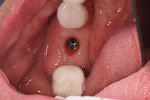
The AnyRidge 5.5 x 8.5 Xpeed implant was then placed with a torque of more than 35 Ncm2. Next, a healing collar was placed to form the emergence profile of the tissue (Figure 10). An alternate method would have been to place a thin, flat cover screw and bury the implant under the tissue. This was not done, because there was excellent initial stability of the implant and, in addition, there were no gaps between the osteotomy and the implant. The flap was closed with 4-0 polyglycolic acid synthetic resorbable suture (Perma Sharp Sutures [Hu-Friedy]). The implant was given 3 months to integrate. The tissue response to the healing collar was excellent for the day of the impression (Figures 11 and 12).
 |
 |
| Figure 16. Radiograph of the custom abutment. | Figure 17. Lateral view of the final crown over the implant in the lower right first molar position. |
 |
 |
| Figure 18. Occlusal view of the final crown. | Figure 19. Radiograph of the completed crown in the lower right first molar position. |
A Miratray Implant Advanced (Hager Worldwide) was used to make an open tray impression for the restorative phase. The Miratray allows me to ready an impression in a matter of seconds, is easy to use, has a clear top to visualize the implants, is very precise, and can be used with all implant systems (Figures 13 to 15). A fast-set, heavy-body Vinylsiloxanether (Identium Heavy [Kettenbach LP]) impression material, with a wash of light-body Vinylsiloxanether (Identium Light [Kettenbach LP]), was used. The author prefers either a digital scan or the open impression technique to minimize human error that can occur in placing impression transfers back into vinyl polysiloxane impressions.
Our dental laboratory team at Aurum Lab (Las Vegas) made a perfect custom abutment and lithium disilicate (IPS e.max [Ivoclar Vivadent]) crown. The lab team also fabricated an acrylic key that fit over the abutment and portions of the adjacent teeth; this was used to carry the abutment from the model into the mouth to ensure the correct orientation to seat the abutment into the implant. The new gold-plated screw in the abutment was finger-tightened. Radiographic verification of the abutment confirmed that it was seated correctly with no visible gaps between the implant and the abutment (Figure 16). The abutment was then torqued to 35 Ncm2. The crown was then cemented with SensiTemp Resin Non-Eugenol Temporary Cement (Sultan Healthcare). The author uses this as the final cement (Figures 17 and 18). The margin, complete seat of the crown, and excess cement removal were radiographically verified (Figure 19).
DISCUSSION
The failure of a final implant crown is bad news for the patient and for any busy practice. The cause of the failure must be determined to know if the remedy is going to be a simple procedure, or a costly and time consuming one. The dental office team member who takes these calls must have training to know what questions to begin asking, how to properly answer the patient’s concerns, and how to schedule the patient appropriately.
A loose screw in a screw-retained abutment or screw-retained crown is a dental emergency. If left loose, the screw could break, and damage could be done to the screw, the abutment, or the implant. This can also cause discomfort, gingival irritation, and patient ill will. The cause of the loosening could be a simple matter of inadequate initial torque, incompatible parts, micromovement and microgaps, or breakage of the actual implant.
CLOSING COMMENTS
This case explored the worst case scenario with a broken implant; however, it had a successful outcome. Part of the success was due to open and direct communication with the patient as to the problems encountered and dialogue with the patient about the work-around options available. The loose screw in this case was not caused by initial inadequate torque. The possible causes included the incompatibility of parts, design failures, and the microgaps and micromovements on the abutment-implant interface. The top of the actual implant had broken, and the only good option to remedy the problem was to explant a fully osseointegrated implant. This was a delicate procedure with serious anatomical considerations of innervation and the desire to be as minimally invasive as possible. Using 3-D cone beam scans, very precise instrumentation for the explantation procedure was illustrated and explained, allowing for a successful new implant to be placed during the same surgical visit. A new style of implant addressed the possible failures of the previous one. Finally, it should be noted that the final implant, custom abutment, and crown were completed only 3 months from the explant date.
Acknowledgment:
The author wishes to thank the dental laboratory team at Aurum Lab (Las Vegas) for their excellent technical work done for this case.
References
- Hahn J. Implant treatment solutions for today’s economy. Lecture presented at: American Dental Implant Association Symposium; September 9, 2011; Miami, FL.
- IDS. Integrated Dental Systems. idsimplants.com. Accessed September 26, 2016.
- Zipprich H. Micro-movements on implant-abutment interfaces—causes and consequences . June 12, 2013. youtu.be/AhsjiYjmTLE. Accessed September 26, 2016.
- Greenstein G, Cavallaro J. Failed dental implants: diagnosis, removal and survival of reimplantations. J Am Dent Assoc. 2014;145(8):835–841.
- Chen L. Master Series 2011. Accelerated Implant Dentistry Education. July 29, 2011; Miami, FL.
- Garg AK. Practical Implant Dentistry. Dallas, TX: Taylor Publishing Company; 1999:119.
Dr. Mitchmore is a graduate of Southwestern University (Georgetown, Texas) and The University of Texas School of Dentistry (Houston). He is also an alumnus of the Pankey Institute (Key Biscayne, Fla), Las Vegas Institute, Schuster Ce
nter (Scottsdale, Ariz), and the Dawson Academy (St. Petersburg, Fla). He is a Master in the AGD and the American Dental Implant Association, and a member of the International Academy of Facial Aesthetics. He is the past chairman of the board of trustees of the American Association of Cosmetic Dentistry’s Charitable Foundation. He is an author, teacher, community leader, and volunteer. Also, he is an instructor in advanced training for dentists and their teams. He can be reached by visiting randymitchmoredds.com.
Disclosure: Dr. Mitchmore reports no disclosures.
Related Articles
Dental Implants: Prosthetic Options
Provisionalization for Implant Dentistry
Latest Trends in Implant Dentistry