Written by: Drs. Mohamed Attia and Gregori M. Kurtzman
Introduction
Rehabilitation of the arch can be challenging, especially when treatment involves edentulation of the remaining dentition on the arch and reduction of the alveolar bone. In these clinical situations, the All-on-X treatment has evolved from freehand treatment to digital flow and guided surgery. Guided surgery with virtual planning has further enhanced the process, making both the surgical procedure and immediate provisionalization easier and more predictable for both the patient and the practitioner. A case is presented below that involved edentulation of the maxillary arch, reduction of the crestal ridge, and placement of an immediate provisional hybrid prosthesis utilizing virtual planning and fabrication of a multi-component guide, as well as prefabrication of the prosthesis.
Case Presentation
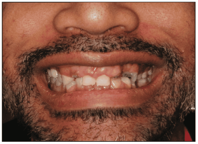
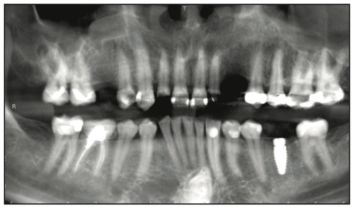
A 41-year-old male patient presented requesting recommendations for his missing teeth, teeth that were breaking down, and an improvement in his smile aesthetics. Examination noted a very “gummy” smile with the maxillary laterals bilaterally decayed with the coronal of the teeth missing, missing left maxillary canine, and decay visible on other maxillary teeth (Figures 1 and 2). Further examination noted a decreased vertical dimension of occlusion (VDO), contributing to the aesthetic issues with the smile. A CBCT was taken, and the panoramic view of the present dentition was evaluated (Figure 3). The maxillary molars had been previously restored with crowns, which, according to the patient, happened several years ago. A periapical lesion was noted on tooth No. 2 in addition to crestal bone loss. Recurrent caries and a missing MOD filling were noted on teeth No. 5; decay on teeth Nos. 7 and 10; marginal breakdown on the amalgam fillings on teeth Nos. 12 and 13; and recurrent caries on the crown margins on teeth Nos. 14 and 15. Radiographically, tooth No. 5 appeared to have a small area periapically. Caries had caused extensive caries under the crown on tooth No. 14. The mandibular dentition was in good condition. An implant was noted at site No. 19 that was unrestored, and had been placed in 2021. Delays resulted as the patient prepared to address the maxillary arch.

The clinical findings were discussed with the patient and he expressed an interest in a fixed restorative treatment. With that in mind, it was recommended that the maxillary arch be edentulated and an All-on-6 approach be utilized rather than try to maintain the posterior maxillary teeth, which would require endodontic treatment in an attempt to preserve them. The patient was informed that the implants would be placed at the time of extraction and that a reduction of the crestal height would be required to aid in eliminating the “gummy” smile and provide sufficient interarch space for the planned prosthetics. An immediate implant, screw-retained, hybrid prosthesis would be placed during the osseointegration phase of treatment before the final prosthesis was fabricated and inserted. As part of the recommended treatment, the implant at site No. 19 would be restored. A written treatment plan was formulated, any questions the patient had were addressed, and the treatment plan was signed by the patient. A scan of the maxillary arch was performed with an iTero scanner (Align Technology) for the planning phase of treatment. The patient was scheduled for the surgical appointment and was dismissed.
Virtual Planning
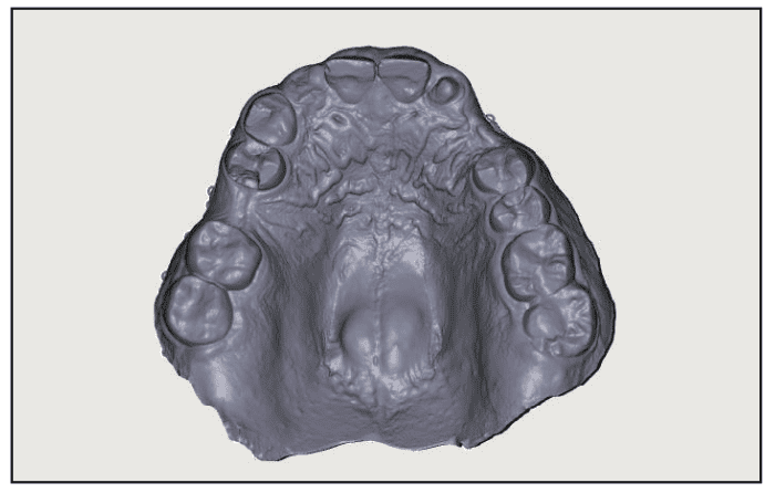
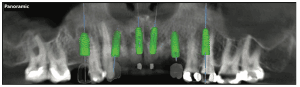
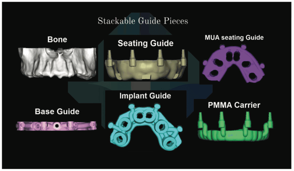
The scan and CBCT were imported into the RealGUIDE software (RealGUIDE Software Suite) (Figure 4). Within the software, implants were planned for site Nos. 4, 6, 8, 9, 11, and 13 based on the available anatomy (Figure 5). Crestal placement level was designed to accommodate the planned crestal bone reduction (Figure 6). Based on the planned multi-unit abutments (MUAs) position utilizing a guided surgery approach, the surgical guides were designed in the software. They included a bone reduction guide, a vertical mount, an osteotomy guide, a timing guide, a PMMA carrier, and a PMMA provisional hybrid (Figure 7). The bone reduction guide would be pinned to the maxilla following flapping the arch to guide the amount of reduction planned. To position the bone reduction guide intraorally and transmit the position designed in the planning software, a vertical mount was created that would fit over the existing dentition, engaging the bone reduction guide through the buccal retention holes. Following fixation of the bone reduction guide to the arch via horizontal fixation screws on the buccal aspect of the arch, the vertical mount was removed. The teeth would then be extracted, and then the crest would be reduced to the level dictated by the bone reduction guide. Following this, an osteotomy guide (ISG) would be placed, engaging the vertical retention holes on the bone reduction guide. A timing guide (TIG) was created to engage the bone reduction guide and facilitate the placement of MUAs into the placed implants, ensuring the correct angle is achieved to parallel the prosthetic axis. A provisional hybrid prosthesis was milled from PMMA, and a carrier (PMMA carrier) was designed to place the provisional restoration in the position related to where the occlusal surface was planned in relation to the opposing arch and desired occlusion.

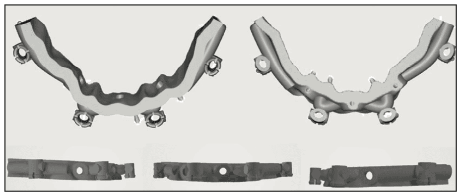
The bone reduction guide was designed to contact the buccal aspect of the arch. Four vertical engagement holes were designed that would be utilized to stabilize the other components (Figure 8). On the outer aspect of the bone reduction guide, 3 stabilization ports were designed to allow vertical screws to fixate the guide to the arch. These were positioned to accommodate the planned MUA positions and allow the bone reduction guide to remain through the placement of the immediate provisional restoration. The osteotomy guide was designed to engage the bone guide and have metal sleeves luted into the guide following 3D printing (Figure 9). The timing guide was also designed to engage the bone guide for stabilization and assure stable positioning based on the virtual planning (Figure 10). These were 3D printed using surgical guides (Carbon3D) clear resin (VeriGUIDE [Whip Mix]) on the Carbon3D printing unit (Carbon3D). To simplify the chairside procedure and decrease chairside time, a PMMA provisional was made following virtual planning (Figure 11, right). A PMMA carrier guide was also designed and printed using the same 3D printing unit as the other guides with Crown X resin (Straumann) to engage the stabilization ports on the bone reduction guide (Figure 11, left).


Surgical Appointment
The patient presented for the surgical appointment and reviewed and signed the consent form. Local anesthetic (Lidocaine 2% without epi and Articaine 4% with 1:100,000 epi) was administered via infiltration from the right tuberosity to the left tuberosity. Oral sedation was performed with one tablet of Triazolam .25 mg, crushed and sublingually under the tongue to improve absorption. The patient sat for about 30 minutes in the operatory in preparation for the surgery.
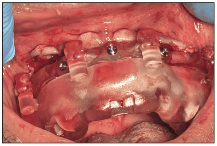
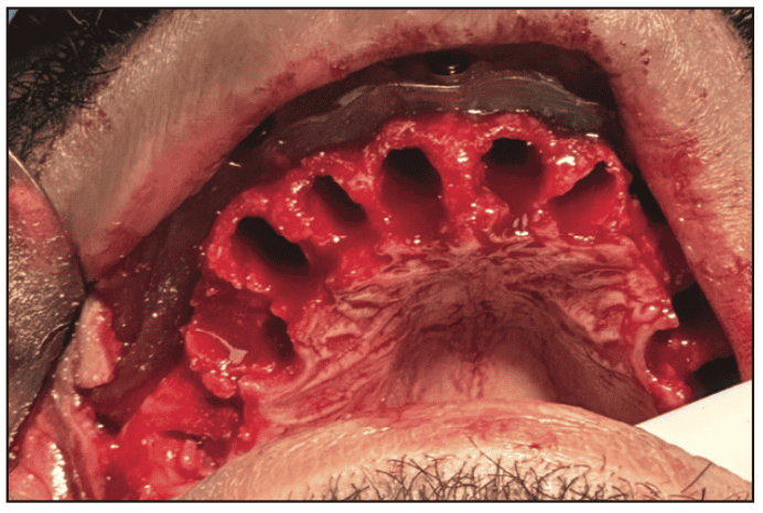
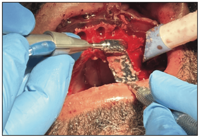
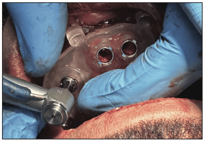
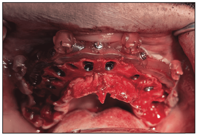
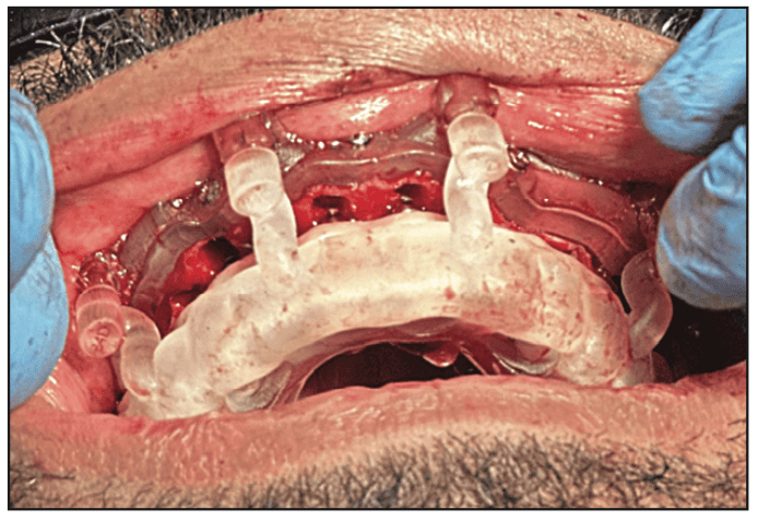
An incision was made on the buccal aspect of the teeth following the sulcus and through the papillae from the right tuberosity to the left tuberosity. An incision was then made connecting the palatal sulcus. A full-thickness flap was performed to expose the maxillary bone high into the buccal vestibule and partially on the palatal aspect of the arch. The vertical mount was inserted into the bone reduction guide and inserted to confirm the planned positioning. This was then inserted over the maxillary dentition and fixation screws were placed through the buccal aspect of the bone reduction guide to fixate it to the arch (Figure 12). The vertical mount was removed, leaving the bone reduction guide in place. The maxillary dentition was atraumatically extracted utilizing elevators and forceps (Figure 13). A straight surgical handpiece and bur were utilized to reduce crestal bone by about 8 mm (Figure 14). The surgical (osteotomy) guide was placed to engage the bone reduction guide. Osteotomies were created using the URIS Pylon surgical kit (URIS) at the planned sites to accommodate, following a guided approach (Figures 15 and 16). Implants were placed through the surgical guide using URIS implants: No. 4 (5 x 10 mm), No. 6 (4 x 11.5 mm), No. 8 (4 x 11.5 mm), No. 9 (4 x 11.5 mm), No. 11 (4 x 11.5 mm), and No. 13 (4.5 x 11.5 mm). The surgical guide was removed (Figure 17), and the timing guide was inserted, fixating it to the bone reduction guide to properly position the MUAs. On Nos. 4, 11, and 13, a 17° MUA was placed, and on Nos. 8 and 9, a 30° MUA was placed. The timing guide was removed and titanium temporary cylinders were placed on each implant. The PMMA provisional was inserted into the PMMA carrier and inserted to engage the bone reduction guide (Figure 18). CompCore resin (Premier Dental) was injected into the occlusal holes between the temporary cylinders and the PMMA provisional. Following the setting of the fixation resin, the provisional and carrier were removed. Additional resin was placed on the gingival aspect of the provisional at the temporary cylinders and polished.

The screws fixing the bone reduction guide to the arch were removed, and the guide was removed. Healing abutments (HS Caps [URIS) were placed on the implants, and the soft tissue was reapproximated and secured with PGA resorbable sutures. A CBCT was taken to document MUA positioning. A scan of the arch was performed with the iTero Lumina scanner (Align Technology) with the HS Caps (Figure 19). The HS Caps were removed, ioConnect scan bodies (URIS) were placed, and the arch was scanned with iTero (Figure 20). The ioConnect scan was imported into TruSuite (TruAbutment). The data exported from ioConnect was then aligned and merged with the HS Cap scan to validate the MUA position. The scan bodies were then removed.


The provisional hybrid prosthesis was inserted and the screws hand tightened to the MUAs (Figure 21). The tissue fit of the provisional prosthesis was not perfect to the soft tissue. It was decided to deliver this as an immediate provisional and fabricate another provisional hybrid following soft-tissue healing. The occlusion was checked and adjusted where needed, and the patient was scheduled for a followup appointment the next day to check the occlusion and other aspects. Antibiotics and pain meds were prescribed.

Postoperative Appointments
The patient presented for the 24-hour postoperative check. He indicated no pain due to the medications that were prescribed. Light swelling was noted in the upper lip. As the patient was a bruxer and clenches, he indicated he purchased an OTC nightguard after his appointment, but it would not seat properly. As recommended, a custom nightguard was fabricated to help minimize pressure on the maxillary arch and its implants during the osseointegration phase of treatment.
An impression was taken, and an Essix-style retainer/guard was fabricated and inserted. The patient was instructed to maintain a soft diet that did not require much chewing, and the provisional hybrid prosthesis was for “looks” only during the healing phase for the implants. The patient was scheduled for the next post-op visit in 1 week.
At the 1-week post-op appointment, some swelling was still present in the upper lip and the soft tissue on the arch appeared to be healing well. The patient was reminded to maintain a soft diet and was appointed for a post-op check in 1 week.
The patient presented for the next post-op check, and the occlusion was checked and adjusted. He indicated he had been comfortable and had no discomfort as the implants and soft tissue heal. The next post-op check was scheduled for 2 weeks.
Provisional Hybrid Prosthesis Appointments
The patient presented 3 weeks post-surgery for scans to create a new provisional hybrid prosthesis with improved soft tissue adaptation compared to the original provisional placed at the time of surgery. The ioConnect scan bodies were placed onto the implants after the provisional prosthesis was removed. Both arches were scanned, the scan bodies were removed, and the provisional prosthesis reinserted. The scans were transmitted to the laboratory to create the new provisional hybrid prosthesis.
Four weeks later, the patient presented, and the current provisional prosthesis was removed. The new provisional hybrid prosthesis was tried in. The prosthesis was seated, but it was noted he was in crossbite. Photos were taken to assist the lab in correcting the crossbite. The old provisional prosthesis was reinserted.
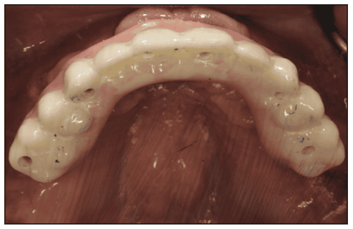
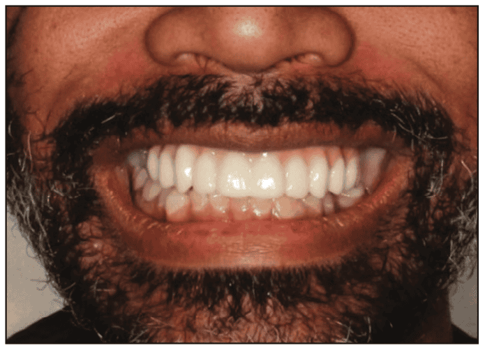
The patient presented a few weeks later for a try-in of the new provisional hybrid prosthesis. The current prosthesis was removed. The new prosthesis would be without Ti-bases to attach the prosthesis to the MUAs, utilizing URIS direct screws. The new prosthesis was inserted and fixated with the URIS direct screws. Fit was confirmed, and good soft tissue adaption to the ridge was noted (Figures 22 and 23). A panoramic radiograph was taken to confirm the seating of the provisional hybrid prosthesis and the bone levels on the implants (Figure 24). The screw access holes on the prosthesis were sealed, and the occlusion was checked and adjusted. The second provisional hybrid prosthesis produced a natural aesthetic result, and the patient expressed satisfaction when shown a mirror, indicating that he was pleased with the outcome (Figure 25). The patient was scheduled to restore the implant at site No. 19. Conversion of the maxillary prosthesis to a final prosthesis would be accomplished in a few months using the virtual design of the second provisional prosthesis to replicate the design for the final prosthesis (Figure 26).


Conclusion
Full-arch treatment with an All-on-X approach can be challenging to achieve as it requires balancing both the patient’s goals and the practitioner’s treatment plan. Virtual planning simplifies the process, aiding in the elimination of surgical issues during implant placement, especially when extractions and ridge reduction are part of the treatment. Guided surgery allows for the virtual planning and design of guides for ridge reduction, implant placement, MUA placement/orientation, and orientation of the immediate provisional hybrid prosthesis. Additionally, the immediate prosthesis can be prefabricated based on virtual planning and design, thereby simplifying chairside time for both the patient and the dentist. Utilization of ioConnect for All-on-X procedures enables highly precise results. An excellent tool for producing repeatable and reliable scans, ensuring accurate data transfer to the dental lab. This aids in prosthetic accuracy and improves communication between the dentist and the laboratory.
ABOUT THE AUTHORS
Dr. Attia is a Master of the Academy of General Dentistry (AGD), Diplomate of the American Board of Oral Implantology, a Fellow of the American Academy of Implant Dentistry (AAID), and a Diplomate of the International Congress of Oral Implantology. He is past president of the Virginia Academy of General Dentistry and currently their CE chair. He also serves on the education councils of the AGD and AAID. He enjoys teaching and mentoring, and speaks on avoiding and managing dental implants complications and conducts hands-on/live surgery courses and workshops. He can be reached at [email protected].
Dr. Kurtzman is in private general dental practice in Silver Spring, Md, and a former assistant clinical professor at University of Maryland in the department of Restorative Dentistry and Endodontics and a former AAID Implant Maxi-Course assistant program director at Howard University College of Dentistry. He has lectured internationally on the topics of restorative dentistry, endodontics, implant surgery and prosthetics, removable and fixed prosthetics, and periodontics. He has more than 900 published articles globally and several ebooks and textbook chapters. He can be reached at [email protected].
Disclosures: The authors report no disclosures.