The edentulous patient has always presented a unique challenge to the restorative dentist. Depending upon the quantity/quality of the residual ridge and the denture bearing area, a patient may or may not be a successful denture wearer. With the addition of osseointregrated implants, even this type of patient can have stable tooth replacements that will function more like his or her natural dentition by creating a firm attachment of the denture base that engages the implant or implant-supported bar yielding a more stable prosthesis.1-3
IMPLANT-SUPPORTED OVERDENTURE: IMPROVING THE PATIENT’S QUALITY OF LIFE
Phase 1—Assessment, Diagnosis, and Initial Therapy
 |
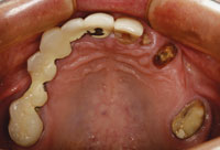 |
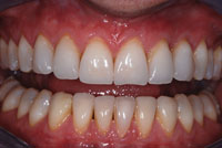
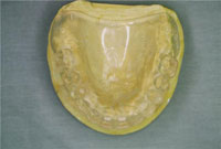
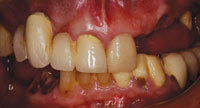
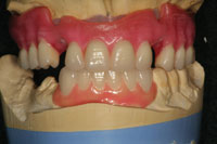
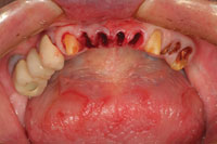
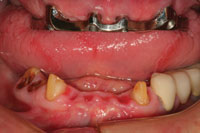
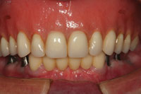
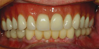
| Figure 1. A preoperative retracted view of the patient’s oral condition prior to treatment. The periodontal assessment and clinical examination revealed a poor prognosis for a majority of the remaining teeth. | Figure 2. A preoperative maxillary occlusal view demonstrated, showing remaining teeth that could not support a fixed prosthodontic solution for a good long-term prognosis. |
 |
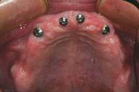 |
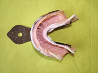
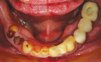
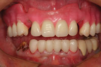
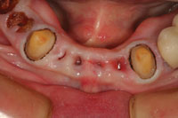
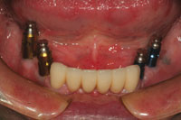
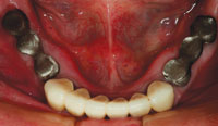
| Figure 3. A preoperative view of the mandibular arch. The temporary prosthesis (teeth Nos. 22 to 26) was removed. Due to the amount of bone loss and recurrent decay, Nos. 22 and 27 were the only remaining teeth with a good prognosis. | Figure 4. Due to maxillary sinus positions, 4 implants were placed between the first premolar regions to support a bar and attachment to secure the maxillary prosthesis. Sinus lift procedures that would have allowed the implants to be placed in a more posterior position were not accepted by the patient. |
In this case, the patient (Figures 1 to 3) presented with a maxillary left quadrant fixed bridge that had come out, requesting that it simply be cemented back into place. After clinical and radiographic examinations, it was determined that the bridge could not be recemented; the patient’s remaining maxillary teeth were periodontally compromised and therefore it was time to think about transitioning to some type of complete removable prosthesis, at least for the maxillary arch. It was hoped that the mandibular cuspids could be retained and used in the final treatment plan to rebuild the case.
After consultation with a periodontist for tooth assessment and implant evaluation, it was recommended that all remaining maxillary teeth be extracted. On the mandibular arch, the canines still had a good prognosis both clinically and radiographically. All remaining mandibular teeth had a poor prognosis and it was recommended that they be extracted. Phase 1 of treatment would involve extraction of the maxillary teeth and socket grafting by the periodontist, along with placement of an immediate transitional full denture. After about 3 months, implant placement would be done.
Due to maxillary sinus limitations and the patient’s unwillingness to have sinus grafting, 4 implants were placed, spacing them in the maxillary central and first bicuspid regions (Figure 4). A treatment denture was delivered by the surgeon at the time of tooth extraction and relined with soft-tissue conditioner. A soft reline material (Ufi-Gel SC [VOCO America]) in the area of the healing abutments prevents transferring pressure (load) to the implants and also assists with retention. After about another 4 months (7 months after the extractions), construction of the definitive prosthesis was scheduled to begin.
Phase 2—Construction of the Maxillary Prosthesis
The vertical dimension of occlusion (VDO) was originally maintained in the immediate denture by mounting the preoperative casts on a semi-adjustable articulator (Denar Combi II Semi Adjustable Articulator [Whip Mix]) using a face-bow transfer and interocclusal records. The maxillary teeth were then removed from the model and the interim prosthesis constructed. Using a traditional removable denture technique, this vertical dimension would be used in the creation of the implant born maxillary prosthesis. With the maxillary interim denture in place, reference points were placed on the nose and chin of the patient using an indelible pencil. A digital caliper (Dentagauge 1 [Erskine Dental]) was used to record the distance between these 2 points as the patient closed to maximum intercuspation using the interim maxillary appliance (Figure 5). The first clinical challenge in this case was to create an interocclusal record without the appliance in place at that same occlusal vertical dimension (OVD). This would allow the master maxillary model for the implant born prosthesis to be mounted in the same relative position to the mandibular arch as was the interim maxillary denture. A poly vinylsiloxane (PVS) registration putty (Extrude Putty [Kerr]) was mixed in a sufficient quantity to cover the maxillary alveolar process and palate. The patient was then instructed to slowly close while his mandible was manipulated into centric relation position (Figure 6). When the premeasured position was reached and verified with the digital caliber, the patient held his lower jaw in this static position until the putty was set. This record allowed the fixture level master impression to be mounted in the same position relative to the mandibular teeth as the intermediate prosthesis. (The goal is to be in the same approximate position as the preoperative vertical dimension of occlusion.) This position was then to be verified phonetically and corrected as necessary at the wax try-in stage.
 |
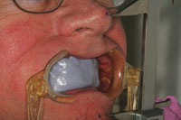 |
| Figure 5. A measurement was taken with a digital caliber of the occlusal vertical dimension (OVD) as it exists with the immediate temporary maxillary denture. The vertical dimension of occlusion (VDO) was estimated in the laboratory from a preoperative mounting of the maxillary and mandibular casts prior to removal of the teeth on the maxillary cast and the fabrication of the immediate maxillary denture. | Figure 6. A bite registration putty was used over the maxillary arch and healing abutments. The patient’s mandible was guided into a position based on the OVD of the transitional denture to approximate that position for fabrication of the wax rim of the implant-born prosthesis. |
 |
 |
| Figure 7. After placement of the impression abutments on the implant platforms, a master impression was taken of the maxillary arch. | Figure 8. This photograph illustrates a very important step that is often overlooked: verification of the accuracy of the master impression using a laboratory-fabricated Duralay (Reliance) index. |
 |
 |
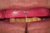
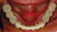
| Figure 9. At the wax-rim stage, the occlusal plane and OVD are evaluated and adjusted as necessary. Also, the smile line and midline of the maxillary central incisors were marked on the rim with a metal instrument. | Figure 10. The maxillary teeth were placed into the wax rim to evaluate tooth position and aesthetics. The cuspids were left out of the wax-up so that the wax try-in could be secured to the implants with screws. |
The fixture level master impression is a combination open- and closed-tray impression. Since the implants in the central incisor region have 3.5 mm diameter platforms, open-tray impression copings are the only type available. The stock tray (Tray Away [Bosworth Dental) was perforated in the area of the open tray impression copings (Figure 7) to allow easy access to clean off the excess impression material over the retaining screws before the impression material set. After the master models were poured-up in the lab, the dental technician constructed a Duralay (Reliance) index to verify in the mouth that the positions of the implants on the master model were indeed accurate and that a passively fitting bar could be constructed on the master model that would precisely fit the patient’s implants (Figure 8). The next step for the dental laboratory team was to construct a wax occlusal rim to be used to take interocclusal records (Figure 9). The position of the midline and the lip-line at the patient’s broadest smile were marked on the wax rim as a reference for the dental technician when placing the maxillary central incisors in the wax rim. Once interocclusal records were completed on the patient, the wax rim was sent back to the dental laboratory for placement of the maxillary teeth. A wax-up of the mandibular anterior teeth on the opposing model will help the dental technician set the maxillary anterior segment in harmony with the proposed position of the mandibular anterior teeth. It will also serve a template for the mandibular anterior provisional restoration (Figure 10).
TREATING THE MANDIBULAR ARCH
At the next clinical appointment, the focus shifted toward the mandibular arch where our treatment plan consisted of using a combination of posterior fixed implant bridges with a conventional anterior 6-unit fixed bridge.
The plan was to construct a provisional stent from the master diagnostic model (Master Diagnostic Wax-Up [Valley Dental Arts]) of the mandibular anterior segment.
 |
 |
| Figure 11. At the mandibular bridge preparation appointment, the mandibular incisors were removed after preparation of the cuspid teeth as bridge abutments. | Figure 12. The completed mandibular provisional bridge. Ovate pontics were made on the restoration that extended into the extraction sites to guide the healing of interproximal tissues. |
 |
 |
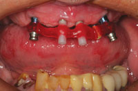
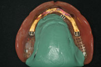
| Figure 13. After several weeks of healing, a master impression was made to fabricate a fixed bridge replacing teeth Nos. 22 to 27. | Figure 14. At the bridge delivery appointment, the maxillary bar was tried in to ensure passive fit. Note healing of the ovate pontic sites 23 to 26. |
 |
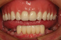 |
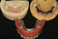
| Figure 15. The completed mandibular fixed bridge, maxillary denture bar, and implant supported maxillary complete denture with ball attachments in place, as ready for delivery. | Figure 16. The maxillary denture and mandibular fixed bridge in place. A mandibular impression and centric records were taken at this time so that a transitional mandibular partial denture could be made to provide posterior occlusion during the next phase of treatment. |
The mandibular incisors were extracted and the mandibular cuspids were prepared as full coverage abutments (Figure 11). Figure 12 shows the maxillary wax rim in place after the completed provisional restoration was cemented to place. Ovate pontic design was used on the provisional restoration to guide the healing of the gingival tissues around the extraction sites. In the centric occlusion position, the maxillary anterior teeth and the mandibular anterior provisional restoration determined the OVD, allowing verification of the space between the arches in the posterior areas where the remaining tooth replacements would eventually reside. After a few weeks, the tissues had healed sufficiently to allow a master impression to be taken for fabrication of a mandibular fixed bridge (teeth Nos. 22 to No. 27) (Figure 13). At the same appointment, the bar that was designed to help retain the maxillary overdenture was tried in to verify a passive fit on the implants (Figure 14). The maxillary overdenture was then processed and the mandibular bridge completed by the laboratory. The plan was to deliver the overdenture and to cement the mandibular anterior bridge prior to beginning the prosthetic procedures for the mandibular posterior implants. The remaining posterior teeth had been extracted, sockets grafted, and implants had been integrating during the try-in process for the maxillary overdenture (Figures 15 and 16). Once delivered, these prostheses would maintain the VDO in the posterior area during the completion of the mandibular reconstruction.
 |
 |
| Figure 17. The mandibular transitional flexite partial denture is delivered. The flexite denture was to be used by the patient during the extraction, socket grafting, and implant integration for the mandibular posterior implants. | Figure 18. After integration of the mandibular posterior implants was completed, a master impression was made. |
 |
 |
| Figure 19. The custom abutments were tried in, and the clearance between the abutments and the opposing occlusion was assessed for space required for implant-born fixed bridges. | Figure 20. An occlusal view of the understructures for the bridges in place on the custom abutments. |
 |
 |
| Figure 21. An occlusal view of the mandibular implant-born fixed bridges in place. Composite resin was placed in the screw access holes after torquing of the screws to the implants. |
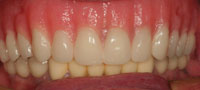
Figure 22. The completed maxillary implant retained overdenture and mandibular fixed reconstruction. There was a difficulty in matching the shade of the denture teeth to the porcelain, even though they were both “A1.” The patient did not have an issue with this minor discrepancy. |
An impression was taken after delivery so that an interim mandibular partial denture could be made to give the patient posterior occlusion until the mandibular implants were ready for uncovery and restoration (Figure 17). Once fully integrated, a master impression of the mandibular implants was made using a closed-tray technique (Figure 18). The treatment plan was to construct 2 3-unit fixed implant bridges to restore the mandibular posterior teeth. Once the custom abutments were completed, they were tried in for fit and to verify the amount of occlusal clearance for the restorations (Figure 19). Since there was a limited amount of space from the top of the implant abutments to the opposing occlusion in this case, it was decided to fabricate screw-retained fixed bridgework. The metal understructures were tried in as well, and radiographs taken to verify a complete seat (Figure 20). Sometimes, the soft tissues can grow over the implant platforms and prevent complete seating of the framework and bridge. In such cases, a dental laser (soft tissue or all laser tissue) can be safely used around the titanium fixtures, unlike electrosurgery, to remove the excess tissue. It is also helpful to check occlusal clearance, with the frameworks in place, to verify the amount of space for the placement of porcelain. If there are some areas where the space is limited, it may be necessary to thin the metal substructure (if possible) to allow for the proper thickness of porcelain.
On the following visit, the mandibular fixed bridges were placed and the implant screws torqued to 25 Ncm using a torque wrench. Then, the screw accesses were filled with composite resin (Figure 21). Figure 22 shows a retracted full-arch view of the completed implant retained reconstruction. The patient wore the maxillary prosthesis successfully for the next year.
Part 1—Bar Overdenture Case Using Bredent Vario Stud Attachment
When Dr. Lowe’s patient came in for his appointment, he was having trouble cleaning and maintaining proper oral hygiene with his restorations. The patient had existing implants on the maxillary arch—4 fixtures from second premolar to second premolar were positioned evenly for final restoration. A transitional denture was in place.
Concluding that overdentures were the best way to address the hygiene issue, Dr. Lowe called Rick Aeziman at Valley Dental Arts laboratory to have a consultation on design options. Considering that the patient required a flange/peripheral extension for adequate lip support, we decided on a fixed removable prosthesis solution after discussing a variety of options. Dr. Lowe had one concern with this solution: in this patient’s case there was a critical lack of vertical height for attaching the prosthesis. For that reason, after studying the casts and checking occlusal dimensions, we chose to use the Bredent Vario Stud Attachment System due to its low profile and excellent retentive properties.
Our first step in the laboratory was to set denture teeth in wax to duplicate the anticipated final result for the patient. This would enable Dr. Lowe to try the presetup in the patient’s mouth to verify overjet, overbite, phonetics, occlusion, and aesthetics. A verification jig was also fabricated in the laboratory to be used to determine whether the analogs, as positioned in the model, correspond correctly to the position of the fixtures clinically.
At the try-in appointment, the doctor verified that the model was accurate chairside, using Pattern Resin LS (GC America). Then, the case went back to the laboratory, where tray adhesives were applied to the denture teeth on the labial and buccal surfaces. The adhesive was allowed to become tacky. Next, a condensation silicone (Sil-Tech [Ivoclar Vivadent]) was applied for the matrices.
Once the Sil-Tech was set, the model was placed in a boil-out tank to melt away the utility wax, leaving the teeth suspended in the matrix. With the teeth suspended, a custom-milled bar was developed in ABF-milling wax (Metalor), using the Degussa F1 milling machine. The wax bar was created with a 2° taper, to allow adequate retention within the perimeters of the verified denture setup.
Then, allowing for the lack of vertical, the Bredent Vario Stud Attachments were placed on the lingual surface of the bar, using a surveyor (Ney) to position the attachments parallel to each other, and to the bar. This process helps ensure proper retention and a precise path of insertion for the final prosthesis.
Once the attachments were set in place, the bar was sectioned in the 5 areas between each implant fixture in order to relieve stress in the wax and resin. With the bar sectioned, the sprues were attached and the bar was luted with Yeti Bordeaux wax, which provided the level of density and dimensional memory (dead wax consistency) that was needed. The bar was then placed in the casting ring, using GC Fujivest II as investment. After pouring the investment, the ring was put in a BEGO Wiropress SL to cure at 4 bars of atmospheric pressure for 10 minutes. Next, the ring was bench-set the ring for one hour, giving the investment time to fully mature, and for any gases to escape. Then, the ring was burned out in an EWL 5646 (KaVo) furnace, starting with the furnace cold and heating it to 1,652° F (a climb rate of 14.2° F per minute, with a 90-minute hold).
Next, the casting was done using a palladium-based alloy (SUPERIOR Alloy [Jensen Industries]) that was selected because of its high tensile strength. The choice of metals here was especially important to the success of this case because of the high occlusal forces involved. The sprues were then sectioned off with a separating disk and the casting was divested using high-pressure aluminum oxide sand.
After verifying the fit under a 10-x-20-power microscope, we determined that the bar did not fit passively, a problem we addressed by sectioning the bar in 2 locations. Using a laser welder (BEGO), we tack welded each section, then removed the bar from the model and flowed in solder (Special High Fusing White Ceramic Solder [Ivoclar Vivadent]), chosen due to its compatibility with palladium-based alloys.
To complete the final milling process, the Degussa F1 milling machine was employed using eucalyptus oil to disperse the heat and to serve as a cutting agent. Polishing steps included the use of a Pink High Shine Polishing Wheel (Brasseler USA), followed by a felt wheel with tripoli to remove fine scratches and blemishes. A final high luster was achieved using rouge on a mounted cotton buff.
A 24-carat gold AGC electroforming process (Wieland) was next, ensuring a zero-tolerance retentive structure. This 24-carat suprastructure was processed directly over the bar for exceptional fit and retention. In the final process, this is attached to the cast denture base by means of tack welding and a special adhesive.
The laboratory’s cast partial specialists then used the BEGO technique with Wironium extra hard alloy to build the cast denture base. The master model was placed on the BEGO Surveyor to eliminate undesirable undercuts and to mark the height of contour, allowing the cast base to draw.
To reproduce the refractory model, BEGO Wiroplus S investment was placed in the BEGO Wiropress SL at 4 bars of atmospheric pressure; this forces the silicone to exactly duplicate the blocked out master model. After 35 minutes in the chamber, the model was separated from the silicone. The silicone was given a “rest” for 20 minutes to allow the material to return from its elongated state to its original dimensions.
A refractory model was then made using BEGO Wiroplus S investment which was mixed under maximum vacuum for 60 seconds. The investment was poured into the silicone mold and placed in the BEGO Wiropress SL at 4 bars of pressure for 20 minutes to complete the set. This produced a highly dense and accurate model. The model was then separated from the silicone and placed in a dry-out oven at 250° for about 20 minutes in order to remove all moisture (the model turns from gray to white as it dries).
When the model had cooled, the design was transferred from the master model to the refractory, using a No. 2 red pencil. Premanufactured BEGO wax patterns were lightly pressed in place on the master model.
The wax-up was then ready to be sprued, invested, burned out to eliminate wax, and cast with Wironium extra hard chrome cobalt alloy. After the ring was cool to the touch, the casting was divested and sandblasted with 80-grit aluminum oxide. The sprues and button were removed and excess flash was trimmed to fit the duplicated model. Then it was electropolished in a solution of sulfuric acid, rinsed in water, and dried. Next, it was fit to the master cast and the bite was checked. Using a polishing wheel (Rubber Polishing Wheel [BEGO]), any scratches and blemishes were removed. Finally, it was buffed to a high shine with a BEGO Felt Polishing Wheel and BEGO Rough & Final Polishing Compound. At this point, the case was ready for denture fabrication.
The teeth were reattached to the cast metal denture base using the indexed polyvinyl matrix with pink utility wax (Henry Schein). When the applied wax reached a solid consistency, the matrix was removed, and the case was ready for final festooning. The prosthesis was then sent to Dr. Lowe for a try-in appointment, where he verified form, fit, function, and aesthetics. Approved by doctor and patient, the case went back to the laboratory for final processing of the acrylic (SR Ivocap Injection System [Ivoclar Vivadent]) to finish the prosthesis.
Part 2—Fixed Implant Retained Mandibular Partial Dentures
Dr. Lowe took a mandibular arch impression fixture level impression and sent it to the laboratory along with an impression of the maxillary overdenture and a PVS centric occlusion record. The impression was poured and a screw-retained bite rim was fabricated, as well as a GC Pattern Resin jig. Implants were placed in the following positions: Nos. 20, 21, 28, and 30. The case was returned to Dr. Lowe, where he took a jaw relation and the model was re-verified utilizing the GC Pattern Resin jig. The case was then returned to the laboratory for fabrication of the frameworks as follows: Nos. 22 to 27 conventional bridgework and Nos. 19 to 21 and Nos. 28 to 30 implant bridgework. The frameworks were verified clinically, and lastly the ceramic was applied for final insertion and delivery.
After about one year, the patient noticed that the maxillary arch denture was not as retentive as when it was first placed. In fact, he had been using adhesive to help retain the prosthesis. The ball attachments were replaced with the most retentive type available to see if the retention of the prosthesis would improve. The patient reported that the denture would feel “loose” after a few weeks, but he could tolerate the retentive quality for a few months at a time. We continued to swap out the attachments, until it was decided that there would be a change in attachment type to see if the retentive quality could be improved.
Part 3—Changing the Attachment to Locators
The patient wore the prosthesis for approximately one year. During that time, the nylon female component began acquiring plaque, and the Bredent balls were showing wear from the insertion and removal process. The obvious solution was to change the female component for the most retentive one available. However, the plaque buildup continued, as did the wear on the ball attachments. Consulting with Valley Dental Arts, Dr. Lowe and his laboratory team determined that a different attachment system was the answer. So, he asked for an interim denture to be made for the patient to use while the new attachments were being positioned on the primary bar.
 |
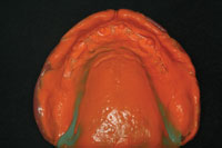 |
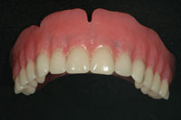
| Figure 23. To allow the dental laboratory team to fabricate a temporary maxillary prosthesis for the patient to wear while the attachments on the bar were changed, an impression of the patient’s maxillary denture bearing area was needed, without the bar in place in the existing appliance. | Figure 24. An intaglio view of the maxillary denture after a master impression was made inside of it. |
 |
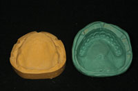 |
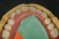
| Figure 25. The impression was poured up in yellow stone on a base. Once the stone was set, the denture was removed and the base trimmed. Notches were made around the base for indexing purposes. | Figure 26. A polyvinylsiloxane putty was used to make an impression of the maxillary denture in place on the model, making sure there was enough material to index the putty accurately to the stone base. This putty impression allowed the laboratory team to make a duplicate denture for the patient to wear while the attachments were changed. |
To make the interim denture, an impression of the patient’s current prosthesis was taken, capturing the soft-tissue landmarks as we would with a reline (Figures 23 and 24). (In addition, a new bite registration was taken.) With this new impression, a thick-based model was poured and allowed to set. Then the model’s base was trimmed and several index points were created (Figures 25 and 26).
Before removing the denture, the doctor fabricated a Sil-Tech putty matrix over the prosthesis, engaging the index points beyond the normal tissue borders. Dr. Lowe removed the putty matrix from the model, articulated the cast, and set the VDO. He then returned the model to the laboratory, where a temporary denture was fabricated for the patient.
Meanwhile, Dr. Lowe decided to replace the ball attachments with a Locator Attachment (Zest Anchors). (An alternative solution could have been to use one of the new replaceable threaded ball attachments from XPdent.) The advantage of the locator style for this patient was that it provides a greater amount of contact between the male and female components improving retention. Furthermore, the attachments are self-aligning, thus minimizing wear.
 |
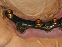 |
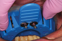
| Figure 27. The maxillary arch denture as altered in order to place Locator attachments (Zest Anchors) that will fit to the altered titanium bar. | Figure 28. The bar with the Locator attachments placed. |
 |
 |
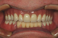
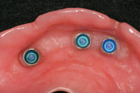
| Figure 29. The Locator attachments in the maxillary denture base. | Figure 30. The completed reconstruction. The attachments were changed using the original bar with the patient using a duplicate prosthesis made from his original denture. This made the transition easy for the patient, with no change in aesthetics or occlusion. |
To make this change, the laboratory team sectioned off the ball attachments from the bar, repolished these areas, and tapped and threaded the locator attachments on the top surface of the bar in tripod fashion (Figures 27 and 28). The prosthesis was then returned to Dr. Lowe, where he related the female component using the direct technique (Figure 29).
COMPLETION of the MAXILLARY PROSTHESIS: SECOND DELIVERY
With the prosthesis successfully transitioned to Locator attachments, the patient had enjoyed improved retention to his maxillary appliance (Figure 30). The authors still do not know why the success with the previous system was less than adequate. It is assumed that, because of the sinus issues and the inability to place implants in a more posterior position, this contributed to the accelerated wear on the attachments as well as the plaque retention wear on the attachments (as noted also by the laboratory team). The Locator solution afforded a more retentive attachment in this case and the patient was able to have a transitional appliance placed that performed adequately during the attachment replacement process.4-10
Acknowledgement
Dr. Lowe would like to thank Mr. Chuck Maragos, CDT, and Mr. Rick Aeziman, CDT, from Valley Dental Arts in Stillwater, Minn, for their expert laboratory workmanship and literary contributions to this article.
References
- van der Bilt A, Burgers M, van Kampen FM, et al. Mandibular implant-supported overdentures and oral function. Clin Oral Implants Res. 2010 Jun 21 [Epub ahead of print].
- Rismanchian M, Dakhilalian M, Bajoghli F, et al. Implant-retained mandibular bar-supported overlay dentures: a finite element stress analysis of four different bar heights. J Oral Implantol. 2010 Jun 14 [Epub ahead of print].
- Turkyilmaz I, Tözüm TF, Tumer C. Early versus delayed loading of mandibular implant-supported overdentures: 5-year results. Clin Implant Dent Relat Res. 2010;12(suppl 1):e39-e46.
- Andreiotelli M, Att W, Strub JR. Prosthodontic complications with implant overdentures: a systematic literature review. Int J Prosthodont. 2010;23:195-203.
- Cehreli MC, Karasoy D, Kökat AM, et al. A systematic review of marginal bone loss around implants retaining or supporting overdentures. Int J Oral Maxillofac Implants. 2010;25:266-277.
- Akca K, Cehreli MC, Uysal S. Marginal bone loss and prosthetic maintenance of bar-retained implant-supported overdentures: a prospective study. Int J Oral Maxillofac Implants. 2010;25:137-145.
- Slot W, Raghoebar GM, Vissink A, et al. A systematic review of implant-supported maxillary overdentures after a mean observation period of at least 1 year. J Clin Periodontol. 2010;37:98-110.
- Fromentin O, Lassauzay C, Abi Nader S, et al. Testing the retention of attachments for implant overdentures—validation of an original force measurement system. J Oral Rehabil. 2010;37:54-62.
- Ellis JS, Burawi G, Walls A, et al. Patient satisfaction with two designs of implant supported removable overdentures; ball attachment and magnets. Clin Oral Implants Res. 2009;20:1293-1298.
- Visser A, Raghoebar GM, Meijer HJ, et al. Implant-retained maxillary overdentures on milled bar suprastructures: a 10-year follow-up of surgical and prosthetic care and aftercare. Int J Prosthodont. 2009;22:181-192.
Dr. Lowe graduated magna cum laude from Loyola University School of Dentistry in 1982 and served there as an assistant professor in operative dentistry until its closure in 1993. Since January 2000, he has been in private practice in Charlotte, NC. Dr. Lowe received Fellowships in the Academy of General Dentistry, International College of Dentists, Academy of Dentistry International, and American College of Dentists, and is a Diplomate of the American Board of Aesthetic Dentistry. He lectures internationally and publishes on aesthetic and restorative dentistry and is a clinical evaluator of materials and products. He also received the 2004 Gordon Christensen Outstanding Lecturers Award. He can be reached at (704) 364-4711 or at boblowedds@aol.com.
Disclosure: Dr. Lowe reports no conflicts of interest.
Mr. Maragos received his associate degree in dental technology from Milwaukee Technical College in 1971. He is a member of the Oral Design Group lead by Willi Geller. He is also one of 3 privileged dental artisans (technicians) to be accredited by the American Society for Dental Aesthetics. Mr. Maragos is chief executive officer of Valley Dental Arts and Valley Dental Technologies and chairman of the Amara Institute. He has received numerous innovation awards and has published various articles on aesthetics, implant dentistry, and co-authored the book Aesthetic and Restorative Dentistry: Material Selection and Technique. He also lectures internationally on the profitability of aesthetic dental materials. He is an active consultant and product evaluator to dental manufacturers in the area of research and development. He can be reached at chuckm@valleydentalarts.com.
Disclosure: Mr. Maragos reports no conflicts of interest.
Mr. Aeziman is vice president of Valley Dental Arts. He oversees case planning, design, and estimates for the implant restorative cases both fixed and removable. He earned his associate’s degree in dental technology from Northeast Metro Tech, and he passed his Certified Dental Technology exam in 1988. Mr. Aeziman mentors technicians and lectures to doctors on implant techniques, design, and protocol on simple and advances restorative cases. He can be reached at rick@valleydentalarts.com.
Disclosure: Mr. Aeziman reports no conflicts of interest.